
Method for facilitating swath height compensation for a printhead

a printhead and height compensation technology, applied in the field of imaging apparatus, can solve the problems of printing defects, grain, horizontal banding, color variations, etc., and achieve the effect of less rejection of printheads during manufacture, less printing defects, and less printing defects

Inactive Publication Date: 2006-03-23
LEXMARK INT INC
View PDF14 Cites 2 Cited by
  • Summary
  • Abstract
  • Description
  • Claims
  • Application Information

AI Technical Summary

Benefits of technology

The present invention provides a method and apparatus for compensating for swath height in a printhead. This is achieved by matching the media feed rate to the printhead swath height. This results in a reduction of printing defects and allows for less precise control of printhead size tolerances during manufacture.

Problems solved by technology

It has been observed that the media feed rate with respect to a particular printhead can cause printing defects, such as grain, horizontal banding, and color variations.

Method used


Image

  • Method for facilitating swath height compensation for a printhead
  • Method for facilitating swath height compensation for a printhead
  • Method for facilitating swath height compensation for a printhead

Examples


Embodiment Construction

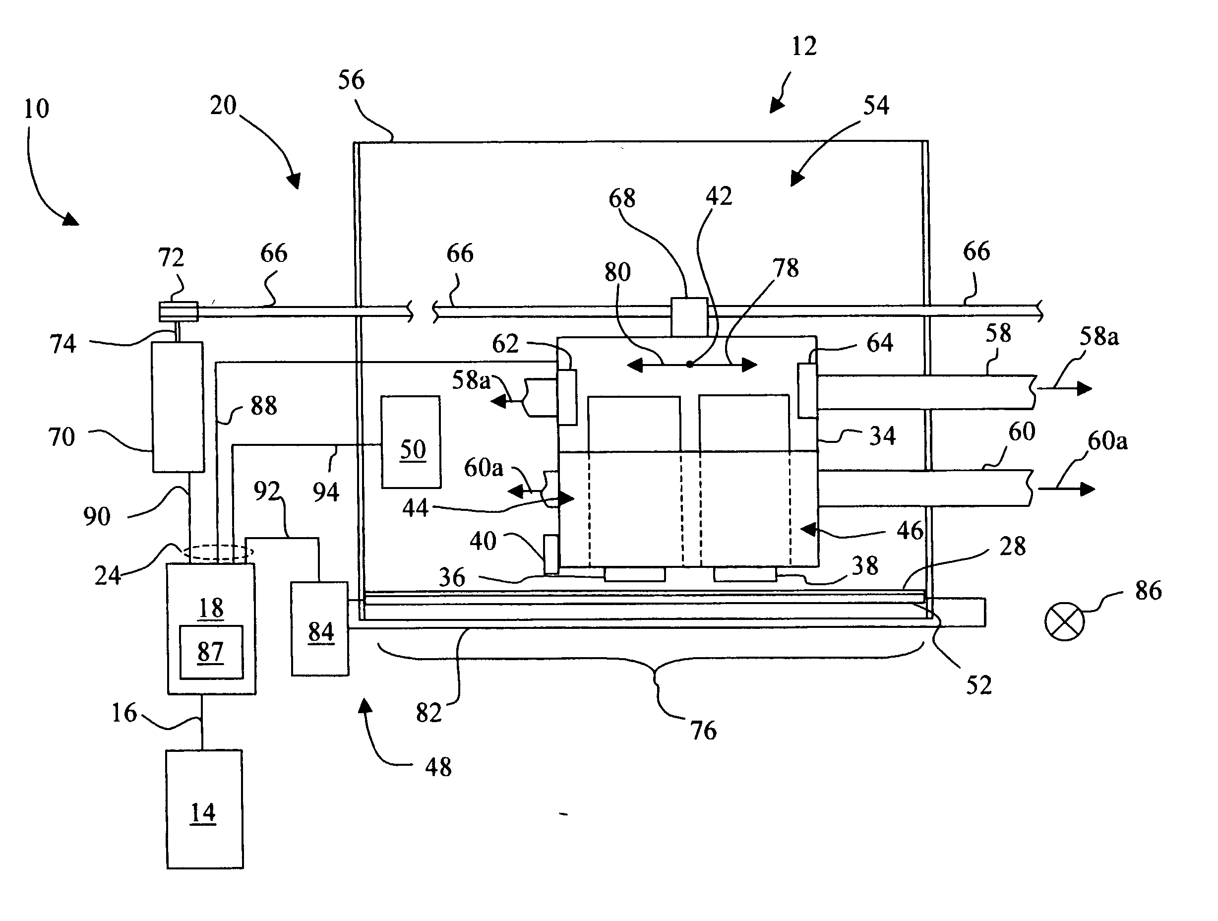
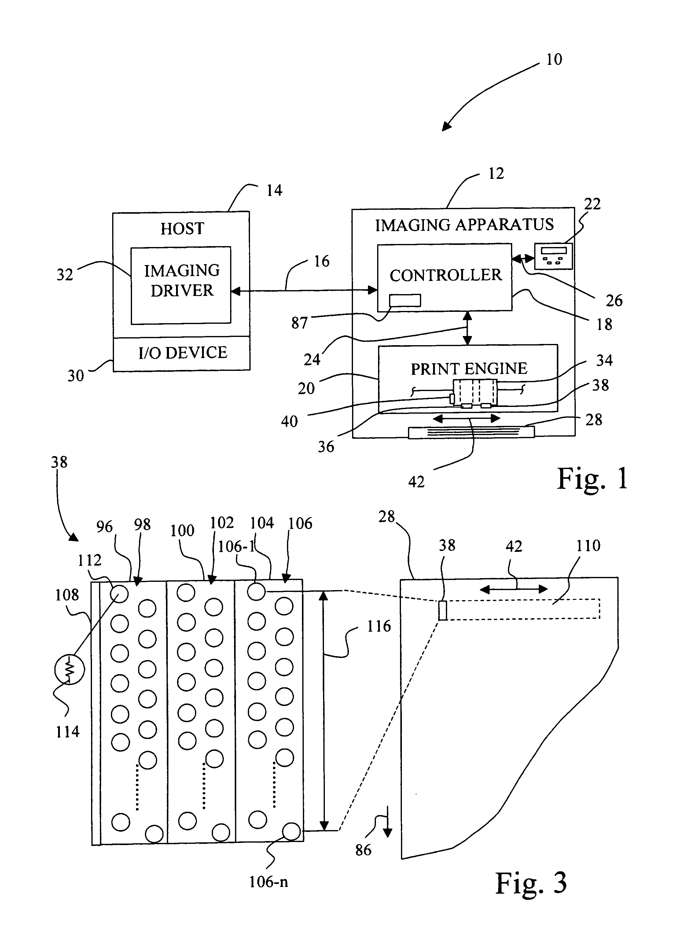
[0021]FIG. 1 is a diagrammatic depiction of a system 10 embodying the present invention. System 10 may include an imaging apparatus 12 and a host 14, with imaging apparatus 12 communicating with host 14 via a communications link 16. As used herein, the term “communications link” is used to generally refer to structure that facilitates electronic communication between two components, and may operate using wired or wireless technology.

[0022] Alternatively, imaging apparatus 12 may be a standalone unit that is not communicatively linked to a host, such as host 14. For example, imaging apparatus 12 may take the form of a multifunction machine that includes standalone copying and facsimile capabilities, in addition to optionally serving as a printer when attached to a host, such as host 14.

[0023] Imaging apparatus 12 may be, for example, an ink jet printer and / or copier. Imaging apparatus 12 includes, for example, a controller 18, a print engine 20 and a user interface 22.

[0024] Contr...


PUM


Abstract

A method for facilitating swath height compensation for a printhead includes determining a nominal swath height for a printhead class; determining a swath height of a printhead belonging to the printhead class; determining a calibration value for the printhead based on a deviation of a swath height of the printhead from the nominal swath height, the calibration value being used to determine a compensated media feed amount for an imaging apparatus; and storing the calibration value in a memory associated with the printhead.

Description

BACKGROUND OF THE INVENTION [0001] 1. Field of the Invention [0002] The present invention relates to an imaging apparatus, and, more particularly, to a method for facilitating swath height compensation for a printhead installed in an imaging apparatus, such as an ink jet printer. [0003] 2. Description of the Related Art [0004] An imaging apparatus in the form of an ink jet printer typically forms an image on a sheet of print media by ejecting ink from at least one ink jet printhead to place ink dots on the sheet of print media. Such an ink jet printer typically includes a reciprocating printhead carrier that transports one or more ink jet printheads across the sheet of print media along a bi-directional scanning path defining a print zone of the printer. The bi-directional scanning path is oriented parallel to a main scan direction, also commonly referred to as the horizontal direction. During printing on each scan of the printhead carrier, the sheet of print media is held stationar...

Claims


Application Information

Patent Timeline
Patent Type & Authority Applications(United States)
IPC IPC(8): B41J25/308
CPCB41J25/308
Inventor MARRA, MICHAEL ANTHONY IIIMAYO, RANDALL DAVID
Owner LEXMARK INT INC
Learn More