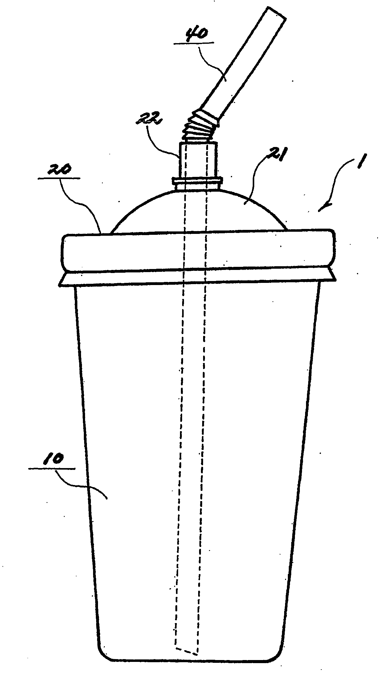
Container for food and beverage
a technology for containers and food, applied in the field of containers for food and beverage, can solve the problems of inability to stably drink contents through the cap, the difficulty of preparing the variety of containers in the small store, and the inability to use the multi-purpose
- Summary
- Abstract
- Description
- Claims
- Application Information
AI Technical Summary
Benefits of technology
Problems solved by technology
Method used
Image
Examples
second embodiment
[0033]FIGS. 3 and 4 show the present invention.
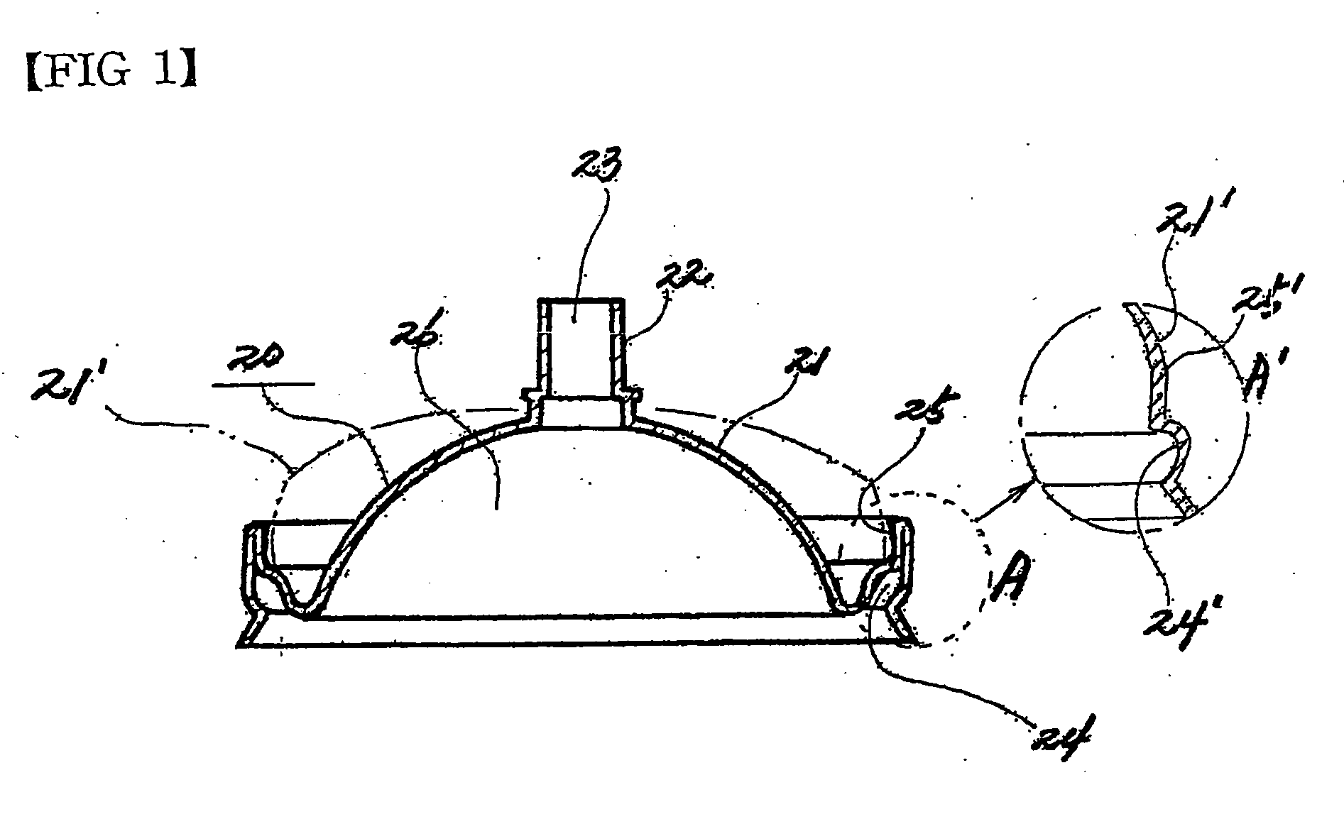
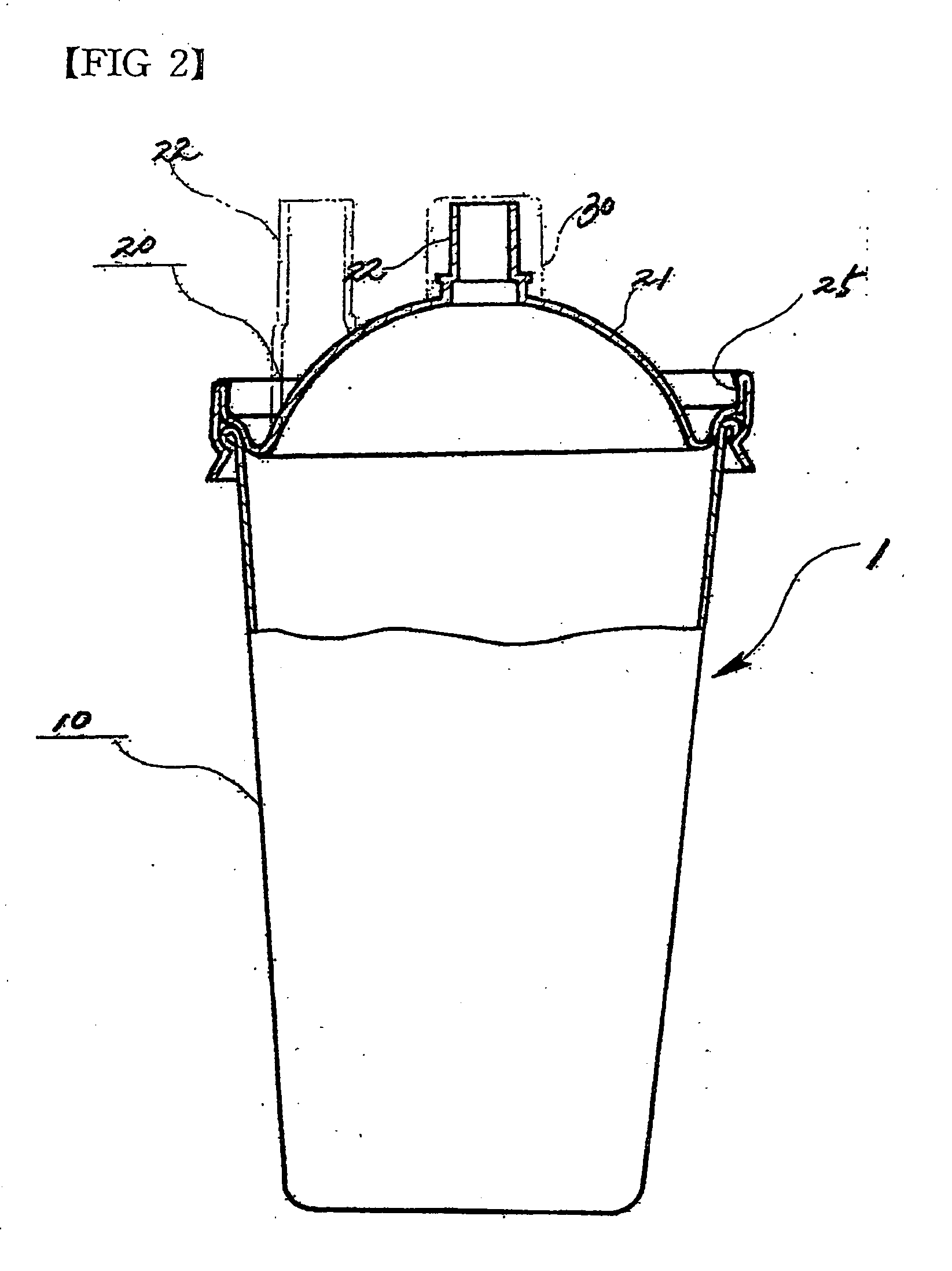
[0034] As shown in the drawings, the food / beverage container 1 is identical to that in the first embodiment.
[0035] However, The hemisphere portion 21 (21′) is provided at an inner bottom with ribs B for guiding the flow of fluid. The ribs B are formed directing the spout insertion hole 23.
[0036] The ribs B prevent the filtering paper from adhering to the inner bottom surface of the hemisphere portion 21. Accordingly, when dripping coffee, the ribs B allow the fluid passing through the filtering paper to effectively flow.
[0037] The operation effect of the present invention will be described hereinafter.
[0038] Referring first to FIG. 5, the cap 20 is assembly on the main body 10. A spouting member 40 is assembled on the spouting portion of the cap 20. When sucking the spouting member 40, the user can drink the contents in the main body 10. At this point, to prevent the main body 10 from being contracted by inner vacuum, the spouting p...
third embodiment
[0048]FIGS. 8 and 9 show the present invention.
[0049] As shown in the drawings, a cap 20 of a food / beverage container according to this embodiment includes a side portion 101 and a top portion 102.
[0050] The side portion 101 is provided at a lower end with a first coupling part 103 for coupling to a coupling circumference 11 of a main body 10.
[0051] A spouting portion 104 provided with a spouting hole 105 is formed on a portion of the top portion 102. A flowing guide passage 106 directing to the spouting portion 104 is formed on the top portion 102. That is, the flowing guide passage 106 is connected to the spouting portion 104.
[0052] The operational effect of this embodiment will be described hereinafter.
[0053] In FIG. 9, there is shown an example where the cap 20 is assembled on the coupling circumference 11 of the main body 10. In FIG. 10, the cap 20 is inversely fitted on the main body 10 and the filtering paper F is dispose din the space 108 of the cap 20. After filling gro...
PUM
| Property | Measurement | Unit |
|---|---|---|
| circumference | aaaaa | aaaaa |
| cylindrical shape | aaaaa | aaaaa |
| dome-shape | aaaaa | aaaaa |
Abstract
Description
Claims
Application Information
 - R&D
- Intellectual Property
- Life Sciences
- Materials
- Tech Scout
- Unparalleled Data Quality
- Higher Quality Content
- 60% Fewer Hallucinations
Browse by: Latest US Patents, China's latest patents, Technical Efficacy Thesaurus, Application Domain, Technology Topic, Popular Technical Reports.
© 2025 PatSnap. All rights reserved.Legal|Privacy policy|Modern Slavery Act Transparency Statement|Sitemap|About US| Contact US: help@patsnap.com


