
Self-sealing male Luer connector with molded elastomeric tip

a technology of elastomeric tip and connector, which is applied in the field of self-sealing male connectors, can solve the problems of harmful to the skin or other tissue of patients, unsafe transfer of drugs from one container to another or to the patient's fluid line, and the free end of the syringe and any residual fluids therein are unsealed and exposed, so as to prevent fluid flow

Inactive Publication Date: 2006-03-16
CAREFUSION 303 INC
View PDF5 Cites 86 Cited by
  • Summary
  • Abstract
  • Description
  • Claims
  • Application Information

AI Technical Summary

Benefits of technology

[0014] In accordance with method aspects of the invention, there is provided a method of establishing a flow path for fluid between a male connector and a female connector, the male connector having a tubular male body with a distal tip, the method comprising inserting the distal tip of the male connector into the female connector, the distal tip of the male connector being elastomeric and resilient and having a transverse size larger than the female connector and a shape differing from the female connector, reshaping the male tip to the shape of the female connector, opening the male tip to establish a fluid passage through the male connector as a result of the reshaping step withdrawing the distal tip of the male connector from the female connector, and closing the male tip to prevent the flow of fluid through the male connector as a result of the withdrawing step.

Problems solved by technology

However, the free end of the syringe and any residual fluids remaining therein are unsealed and exposed.
Yet a further example is in the oncology area where certain drugs have great beneficial effect when confined to the circulatory system of a patient, yet are harmful to the skin or other tissue of a patient.
Transferring such drugs from one container to another or to the patient's fluid line can be hazardous if seals are not present.

Method used


Image

  • Self-sealing male Luer connector with molded elastomeric tip
  • Self-sealing male Luer connector with molded elastomeric tip
  • Self-sealing male Luer connector with molded elastomeric tip

Examples


Embodiment Construction

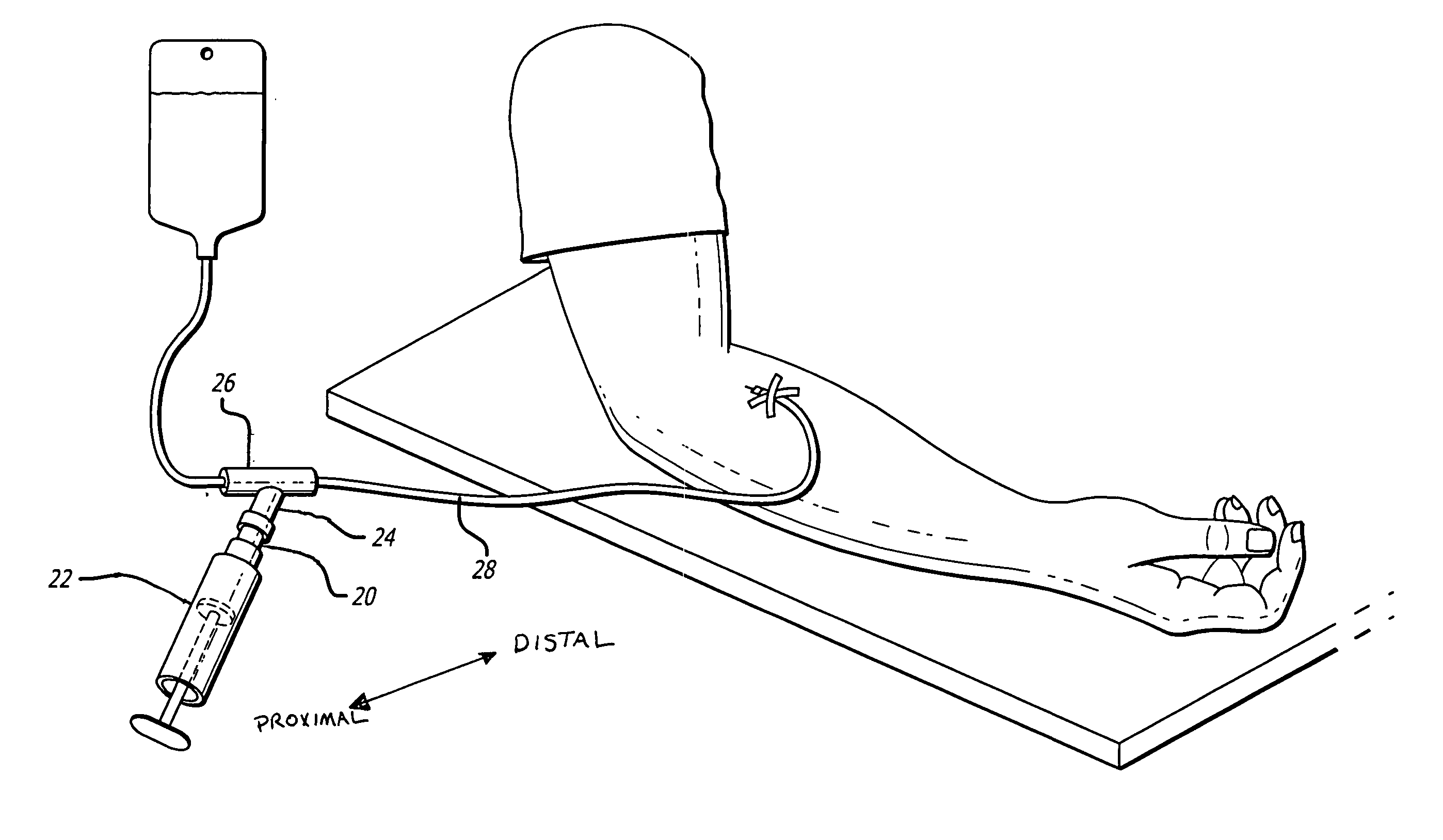
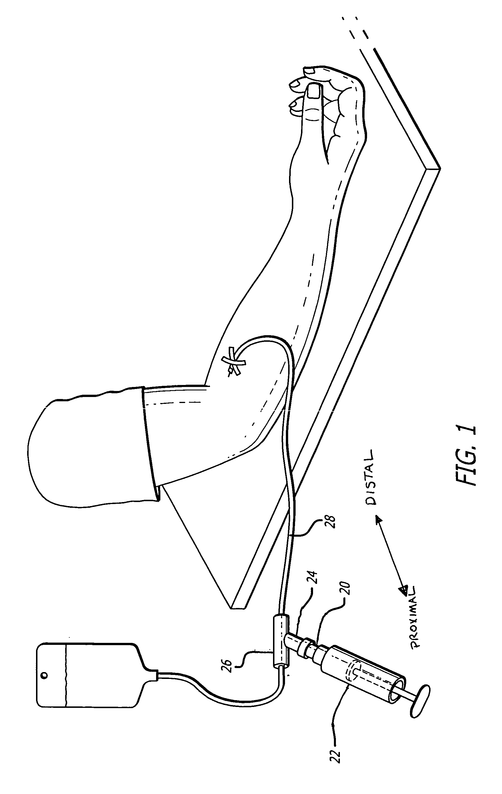
[0031] Referring now to the drawings in more detail, wherein like reference numerals designate corresponding or like elements among the several views, there is shown in FIG. 1 a self-sealing male Luer connector 20 in accordance with aspects of the present invention. In this embodiment, the male Luer connector is mounted at the distal end of a syringe 22 and operably connected to the proximal end of a female Luer connector 24 configured on a Y-site 26 for the administration or withdrawal of fluids through the I.V. line 28. It should be noted that for purposes of convenience in reference, “distal” is meant to refer to the direction toward the patient and “proximal” is meant to refer to the direction away from the patient, or toward the syringe or other collection or dispensing device.

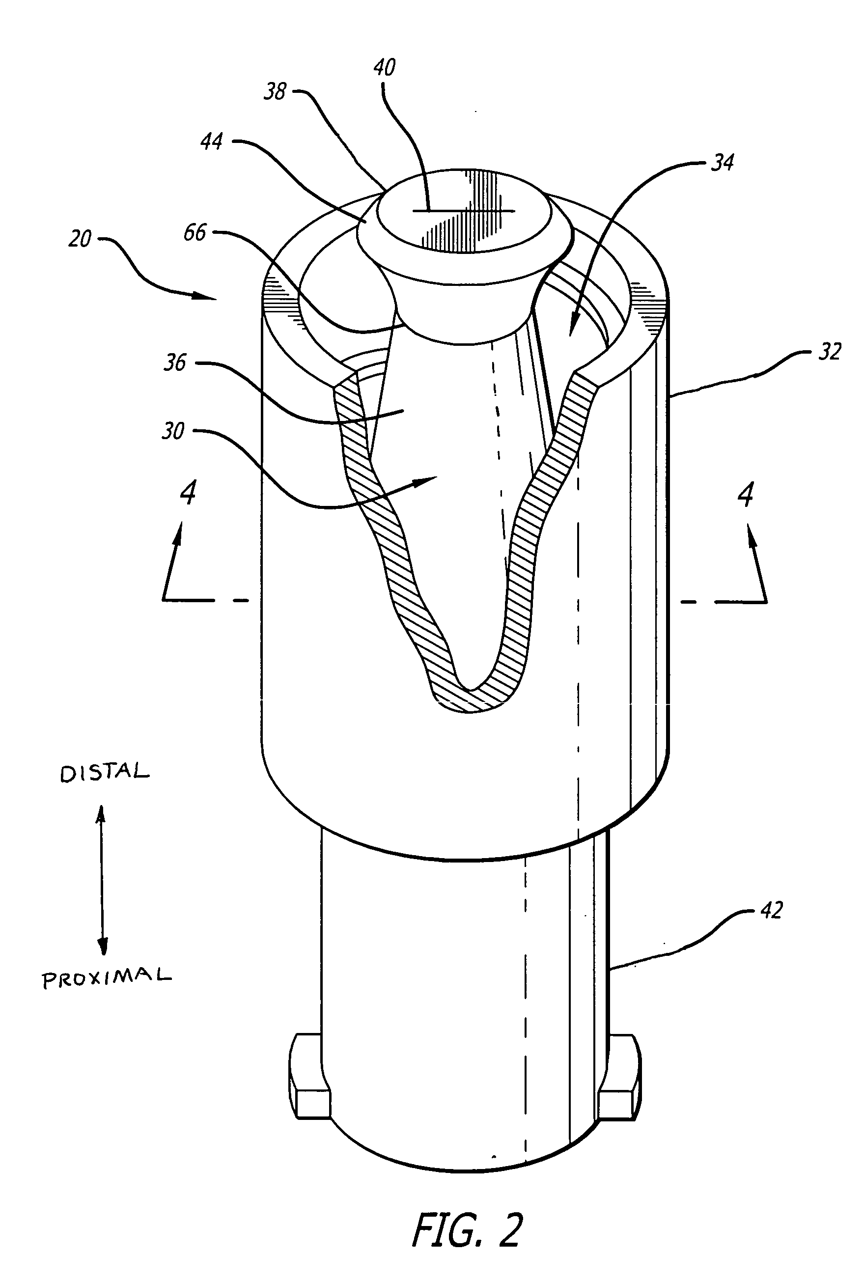
[0032] Referring to FIG. 2, there is shown a perspective view, partially in section, of an embodiment of the self-sealing male Luer connector 20 in accordance with aspects of the present invention. The m...


PUM


Abstract

A self-sealing male connector includes a tubular male body and an elastomeric resilient tip disposed on the distal end of the tubular male body. The elastomeric tip has a transverse size that is greater that the size of a female connector and a shape that differs from the female shape so that engagement of the two will result in reshaping the male tip to the shape of the female flow channel and the male will create a seal with the channel. The male tip is formed with a slit and a hollow core that provides a flow passage formed in the male body. As the male tip is reshaped due to engagement with a female connector, the slit opens to establish fluid flow through the male connector. In one embodiment, the transverse shape of the male tip is elliptical having a major axis along which the slit is formed. In one embodiment, the male tip is oversized in all transverse dimensions and forms an edge seal with the female connector at first contact. The proximal end of the male connector may be configured as a conventional female connector, a blood collection device, or other device. The male body can have a Luer shape.

Description

BACKGROUND OF THE INVENTION [0001] The present invention generally relates to medical connectors used in conducting medical fluids and more specifically to self-sealing male connectors. [0002] The self-sealing medical connectors presently known and used in the art are generally designed to be connected to a patient's intravenous (“IV”) or gas sampling line, drug or solution source, or other medical device such that the connector's seal operates to trap all fluid on the side of the connector toward the patient or other device. As such, the typical connector has an unsealed male connector on one end that remains connected to the patient's IV line, fluid source or other device and a self-sealing female connector on the opposite free end of the connector through which a syringe or other such device may be engaged. [0003] In use, the syringe or other device having a male connector is connected to the female end of the connector to push or pull fluids through the connector, as when medica...

Claims


Application Information

Patent Timeline
Patent Type & Authority Applications(United States)
IPC IPC(8): A61M31/00
CPCA61M39/26
Inventor PHILLIPS, JOHN C.
Owner CAREFUSION 303 INC
Learn More