
Blind structure

a technology of blind structure and sash, which is applied in the direction of shutters/movable grilles, door/window protection devices, draperies, etc., can solve the problems of limited function, inability to provide partial light effect or perspective views outside when fully expanded, and inconvenient operation, etc., to achieve efficient boost the function of the roman blind thereo

Inactive Publication Date: 2006-03-09
SOLTEAM ELECTRONICS
View PDF3 Cites 22 Cited by
  • Summary
  • Abstract
  • Description
  • Claims
  • Application Information

AI Technical Summary

Benefits of technology

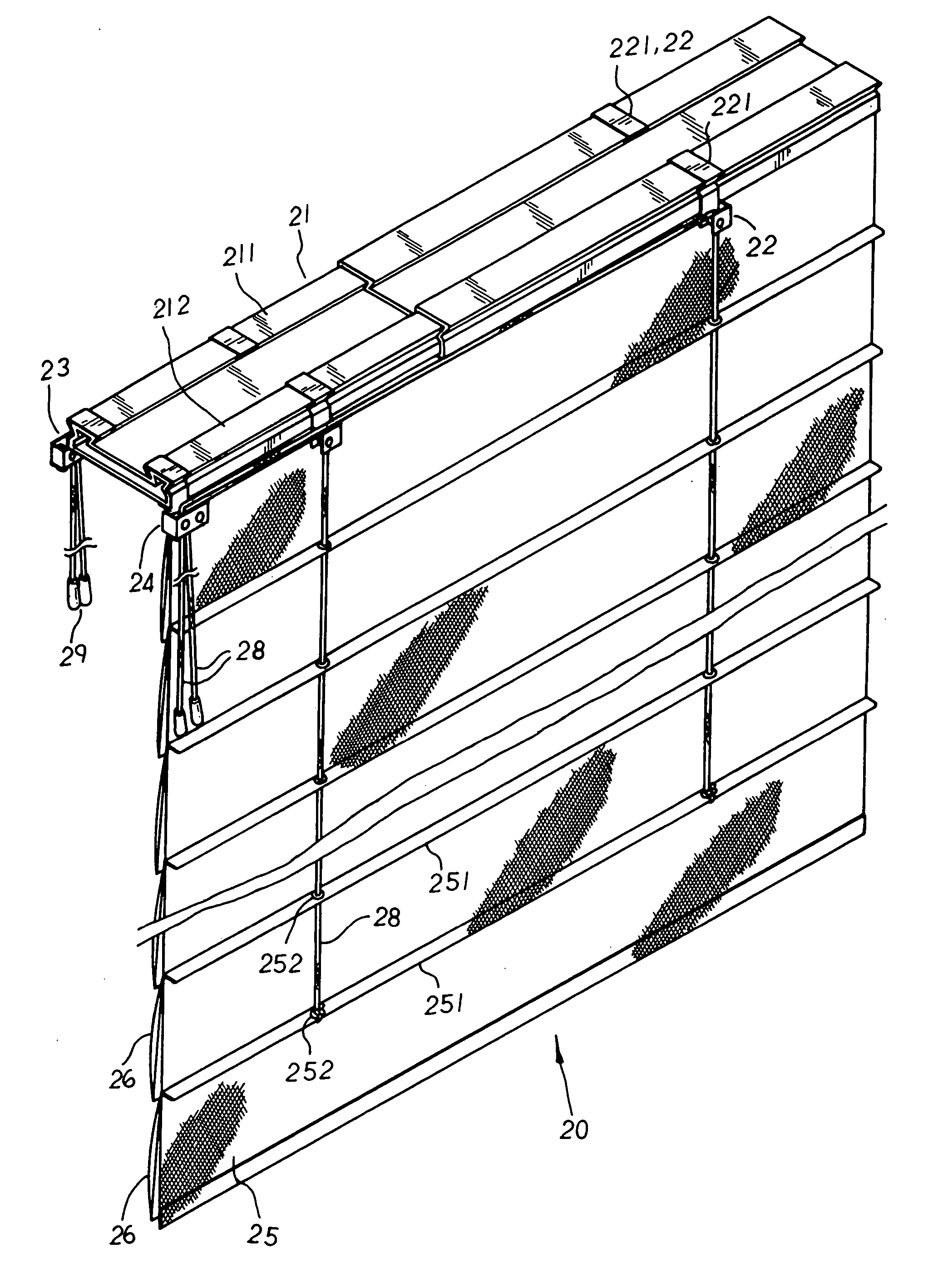
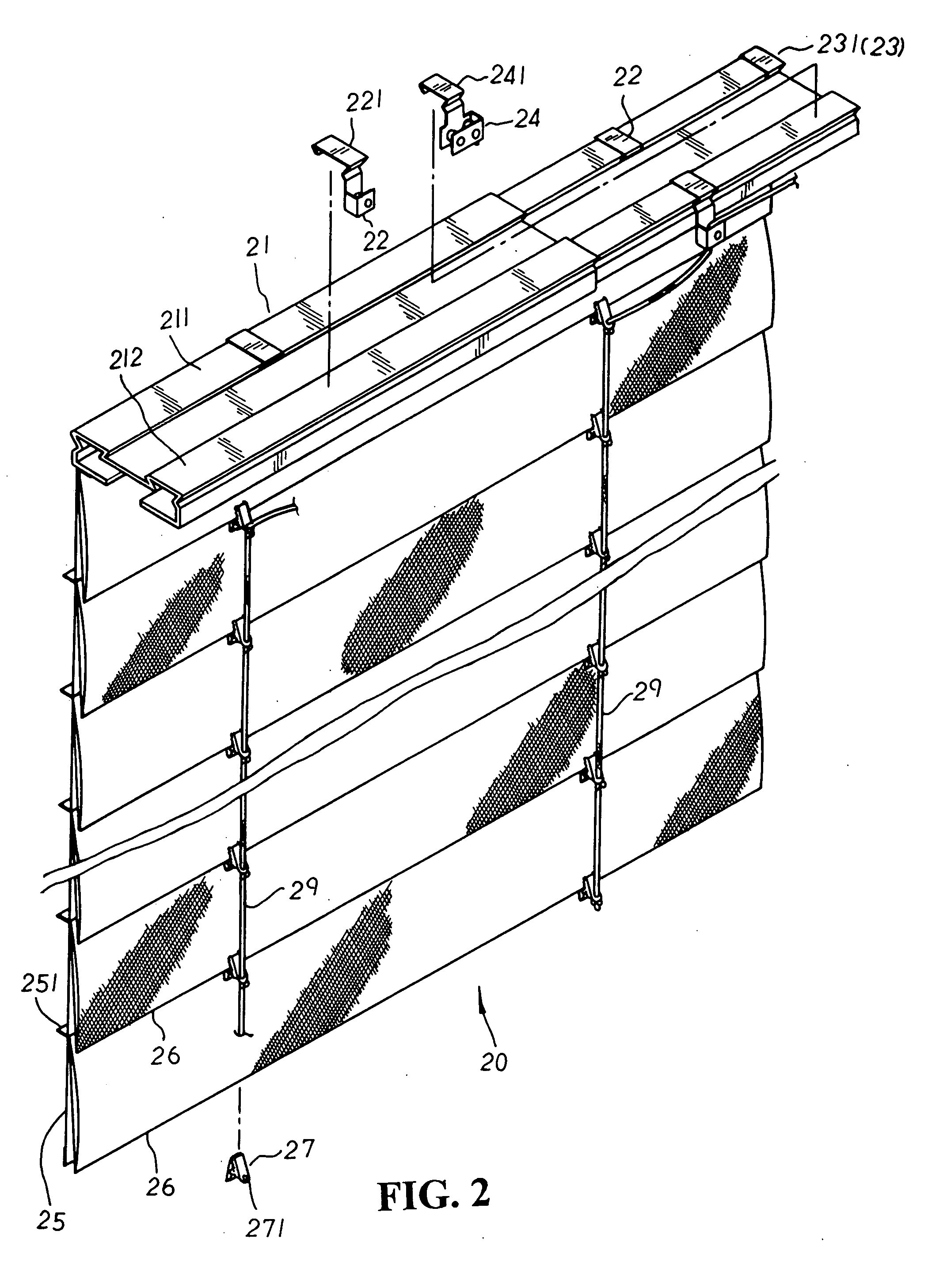
[0004] It is, therefore, the primary purpose of the present invention to provide an improved blind structure, including a Roman blind made up of a light-passable blind body fixedly attached to one side at the bottom of a head-rail to be colleted or expanded by pull cords, and a plurality of black-out blind pieces equidistantly sewed at one side of the light-passable blind body from top to bottom wherein at the bottom edges of the black-out blind pieces are detachably mounted a plurality of movable members vertically lined up for actuation cords to sequentially thread there-through and tie up thereto respectively; whereby, the black-out blind pieces are raised upwards by the actuation cords towards one side of the head-rail to reveal the light-passable blind body in sections, permitting light to come partially indoors according to the position of the uplifted black-out blind pieces or views outside to be seen there-through. Thus, the Roman blind can not only be completely collected or expanded in a total black-out status, but can also be synchronically adjusted to provide partial light and partial black-out effects, efficiently boosting the function of the Roman blind thereof.
[0005] It is, therefore, the second purpose of the present invention to provide an improved blind structure wherein via the number of the actuation cords drawn upwards and the movable members or guide sliding seats of the head-rail that are detachably mounted and freely adjusted in positions, the black-out blind pieces can be flexibly lifted upwards in any angles, permitting the light-passable blind body to reveal versatile perspective spaces accordingly. Thus, the Roman blind can be variably operated to fit to the needs of different users so as to provide a more human-centered design and achieve the best using condition thereof.

Problems solved by technology

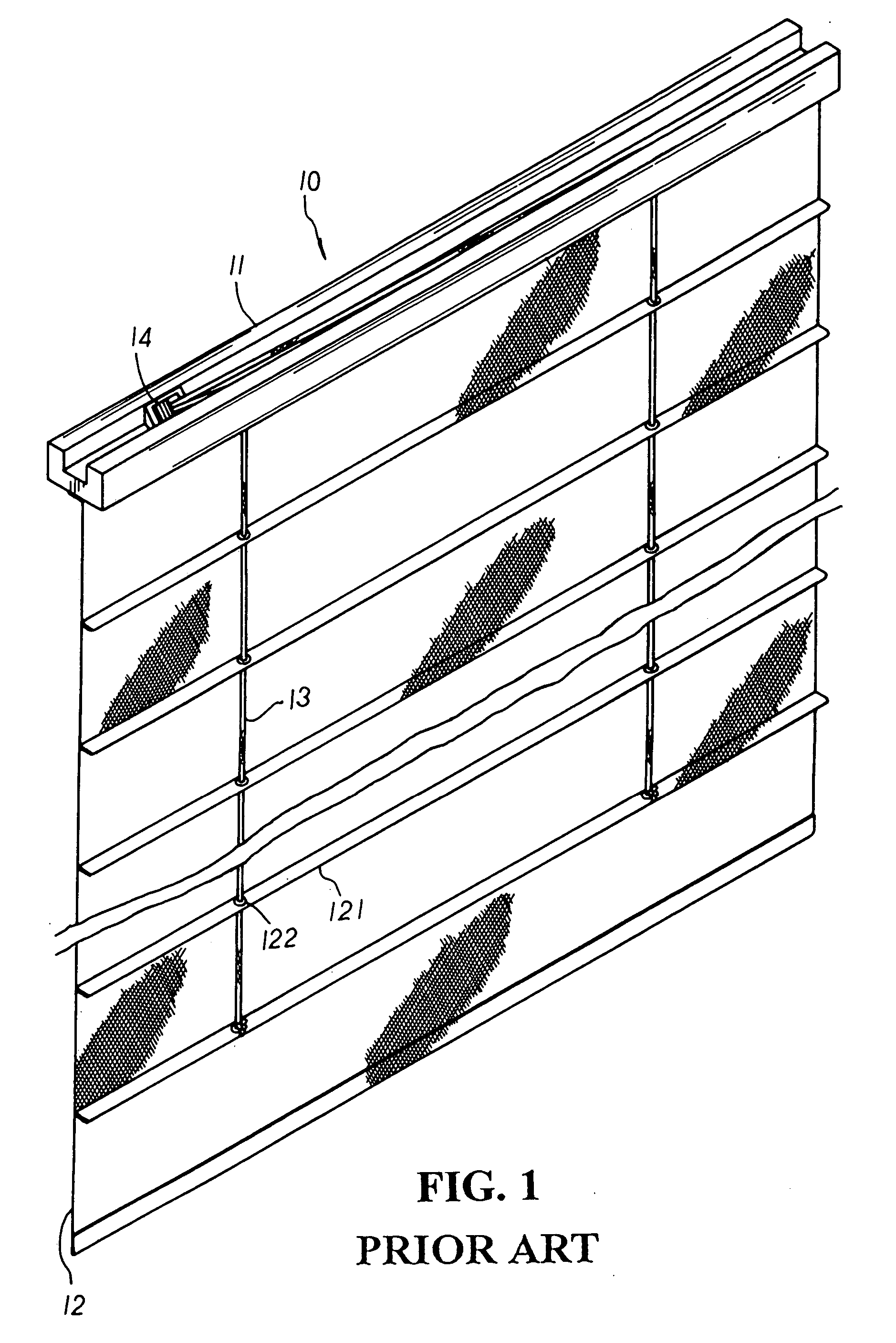
There are some drawbacks to such conventional Roman blind structure.
Thus, the conventional Roman blind 10, unable to provide partial light effect or perspective views outside when fully expanded, is quite limited in function.

Method used


Image

  • Blind structure
  • Blind structure
  • Blind structure

Examples


Embodiment Construction

[0012] Please refer to FIGS. 2 to 3 inclusive. The present invention is related to an improved blind structure, including a Roman blind 20 made up of a head-rail 21 having a first engaging section 211 and a second engaging section 212 symmetrically extending at both top lateral sides thereof for a plurality of guide sliding seats 22 each having a coupling part 221 to be mounted thereto respectively. A pull cord positioning seat 23 with a fixing part 231 and an actuation cord positioning seat 24 with a locating part 241 are symmetrically mounted at one end of the first and the second engaging sections 211, 212 thereof respectively. A light-passable blind body 25 is fixedly attached to the bottom side of the head rail 21 in alignment with the first engaging section 211 thereof, and at the rear side of the light-passable blind body 25 thereof are equidistantly sewed from top to bottom a plurality of folding edges 251 each having cord-passage rings 252 properly riveted thereon for pull ...


PUM


Abstract

An improved blind structure includes a Roman blind having a head-rail made up of a first and second engaging sections symmetrically extending at both top lateral sides thereof for a plurality of guide sliding seats to be respectively mounted thereto wherein a pull cord positioning seat and an actuation cord positioning seat are symmetrically joined at one end of the first and the second engaging sections thereof respectively, and a light-passable blind body is fixedly attached at the underside of the head-rail in alignment with the first engaging section thereof to be collected or expanded via pull cords. A plurality of black-out blind pieces are sequentially sewed in an equal space at one side of the light-passable blind body from top to bottom thereof, and at the bottom edges of the black-out blind pieces are detachably mounted a plurality of movable members that, each having a retaining through hole disposed thereon, are vertically lined up for actuation cords to sequentially thread there-through and tie up to each retaining through hole thereof respectively before winding around the actuation cord positioning seat to suspend downwards there-from. Therefore, the black-out blind pieces are raised upwards by the actuation cords towards one side of the head-rail to reveal the light-passable blind body in sections so that light can come partially indoors according to the position of the uplifted black-out blind pieces, efficiently boosting the function of the Roman blind thereof.

Description

BACKGROUND OF THE INVENTION [0001] The present invention is related to an improved blind structure, including a Roman blind made up of a light-passable blind body fixedly attached to one side at the bottom of a head-rail to be colleted or expanded by pull cords, and a plurality of black-out blind pieces sequentially fixed in an equal space at one side of the light-passable blind body from top to bottom thereof wherein at the bottom edges of the black-out blind pieces are detachably mounted a plurality of movable members with retaining through holes disposed thereon that are vertically lined up for actuation cords to sequentially thread there-through and tie up thereto respectively; whereby, the black-out blind pieces are raised upwards by the actuation cords towards one side of the head-rail to reveal the light-passable blind body in sections so that light can come partially indoors according to the position of the uplifted black-out blind pieces, efficiently boosting the function o...

Claims


Application Information

Patent Timeline
Patent Type & Authority Applications(United States)
IPC IPC(8): A47H5/00A47H5/08A47H23/04E06B9/24E06B9/264E06B9/40
CPCE06B9/264
Inventor NIEN, LESLIE
Owner SOLTEAM ELECTRONICS
Learn More