
Quick release buckle

a quick release and buckle technology, applied in the field of buckles, can solve the problems of affecting the safety of harness users, failure of belt connections in buckles, and failure of buckle components, so as to improve the reliability reduce manufacturing costs, and increase the strength of quick release buckles.

Inactive Publication Date: 2006-03-09
GARRISION TOOL & DIE
View PDF20 Cites 44 Cited by
  • Summary
  • Abstract
  • Description
  • Claims
  • Application Information

AI Technical Summary

Benefits of technology

[0010] Another object of the invention is to improve the reliability of a quick release buckle.
[0011] A further object of the invention is to reduce the cost of manufacturing and assembling a quick release buckle.
[0012] Yet another object of the invention is to increase the strength of a quick release buckle housing.

Problems solved by technology

Buckle retention failures and belt retention failures are typically of greater concern than buckle release failures.
In this instance, failure of the buckle connection could result in harm to the harness user.
Failure of the belt connection in a buckle also can have serious consequences.
One cause of failure in a quick-release buckle is malfunctioning of component parts in the buckle.
Such malfunctioning can result from failure of the parts, for example, due to excessive wear, or to failure of otherwise functional parts to interface properly due to the complexity of the required interface.
That is, increasing the complexity of a mechanism generally increases the probability of failure for the mechanism.
Typically, moving parts and parts operating under stress in a device are more likely to suffer excessive wear.
The rotation causes wear on the cam surface and rivet surface that are in contact.
In particular, wear on the rivet can cause the rivet to fail.
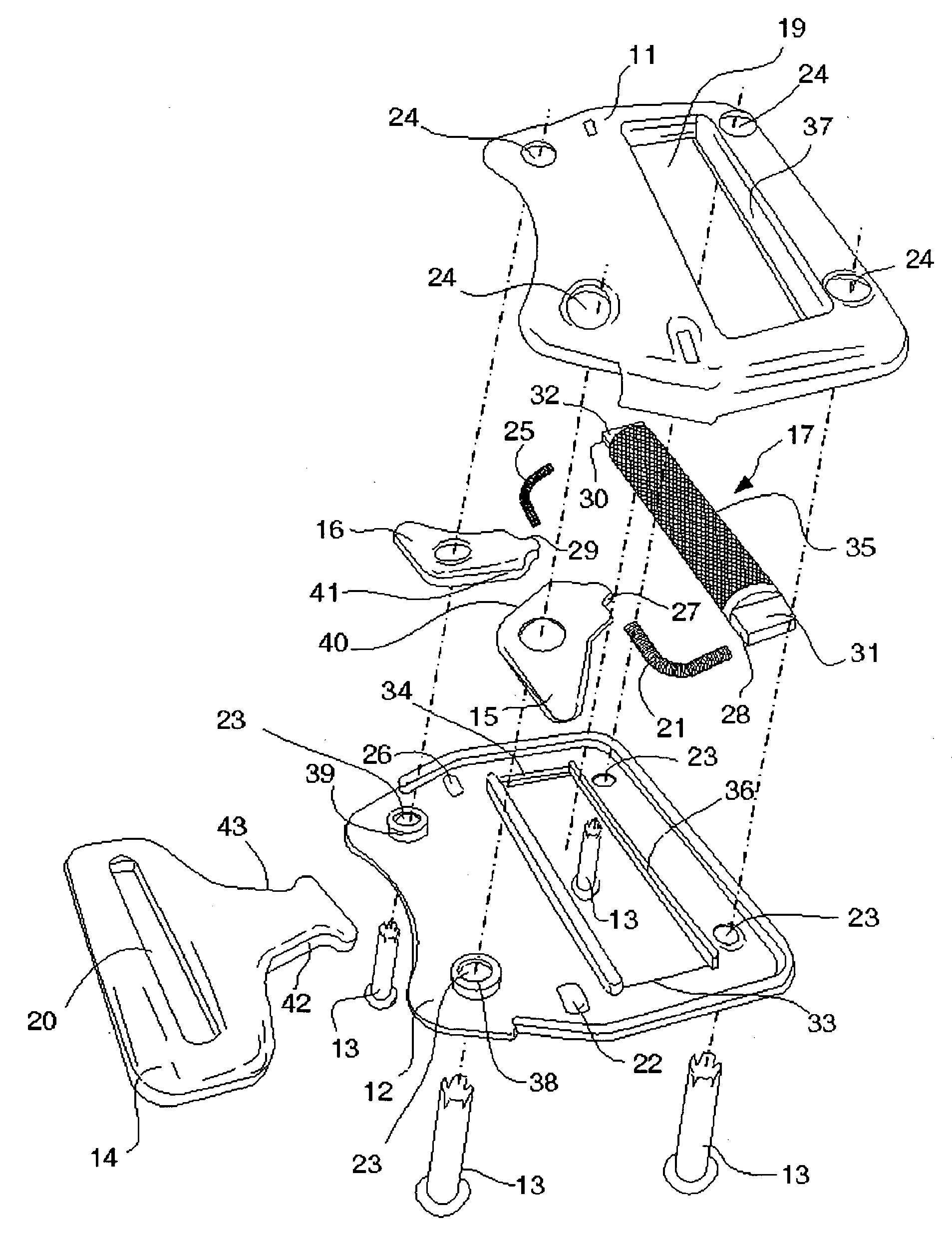
Springs 4 and 5 both move and operate under stress, and therefore, may have an increased likelihood of failure.
Increasing the parts count in a quick-release buckle also can increase the material cost for the buckle.
Increasing the complexity and parts count in the buckle can increase the difficulty and cost of assembling the buckle as well, i.e., labor costs.
Unfortunately, the outer plates may collapse if an excessive force is applied to the rivets, thereby preventing cam rotation.
Failure of the cams to rotate would result in a non-functioning buckle.

Method used


Image

  • Quick release buckle
  • Quick release buckle
  • Quick release buckle

Examples


Embodiment Construction

[0020] At the outset, it should be appreciated that like drawing numbers on different drawing views identify identical, or functionally similar, structural elements of the invention. While the present invention is described with respect to what is presently considered to be the preferred aspects, it is to be understood that the invention as claimed is not limited to the disclosed aspects.

[0021] Furthermore, it is understood that this invention is not limited to the particular methodology, materials and modifications described and as such may, of course, vary. It is also understood that the terminology used herein is for the purpose of describing particular aspects only, and is not intended to limit the scope of the present invention, which is limited only by the appended claims.

[0022] Unless defined otherwise, all technical and scientific terms used herein have the same meaning as commonly understood to one of ordinary skill in the art to which this invention belongs. Although any...


PUM


Abstract

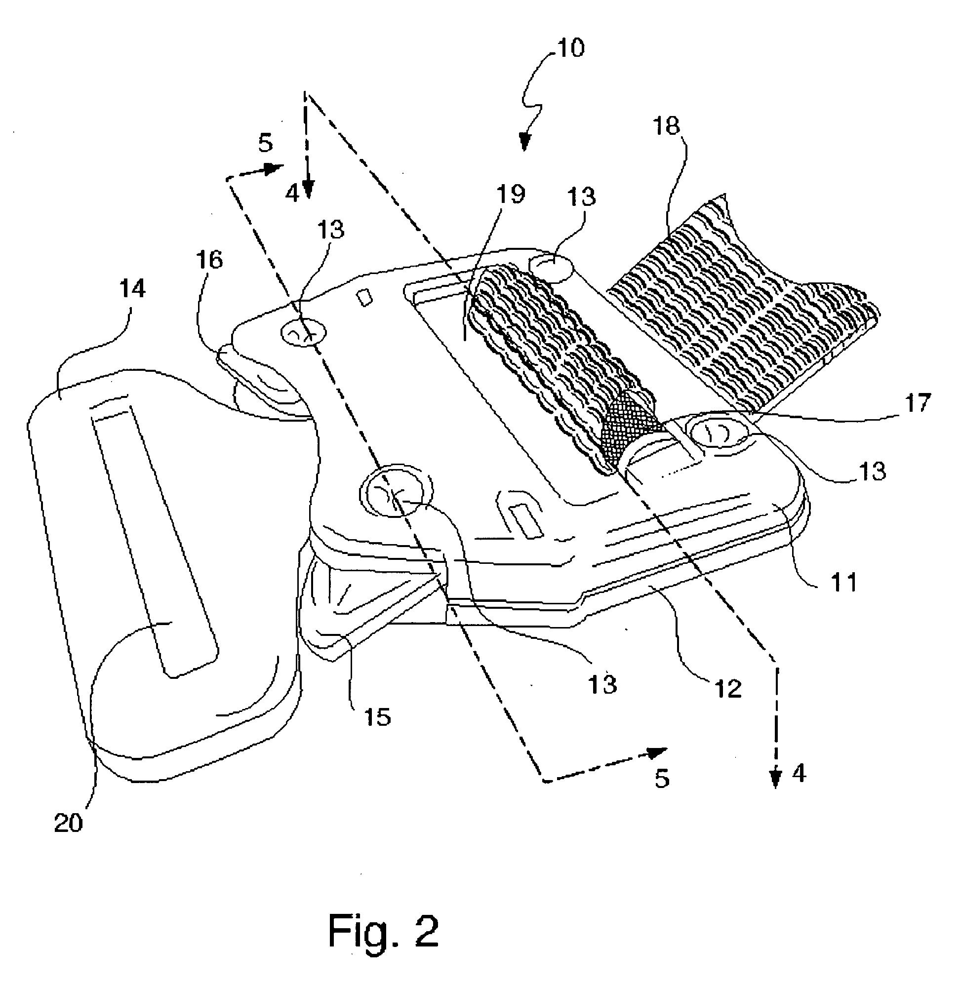
A quick release buckle assembly having a housing, two cams, a knurl bar, and two springs. Each spring is operatively arranged to engage both a respective cam and the knurl bar. The housing includes integral bearing walls for the cams.

Description

FIELD OF THE INVENTION [0001] The present invention relates generally to buckles, more specifically to a quick release buckle, and, even more particularly, to a quick release buckle used on a safety harness. BACKGROUND [0002] As is well known, quick release buckles have applications across a wide variety of fields. Examples include but are not limited to automobile / airplane seat belts, backpacks, parachute packs, and safety harnesses. Combining secure retention and quick-release capability is a common goal for these buckles. [0003] Reliability is critical for quick release buckles. Three facets of reliability are: retaining the buckle connection; retaining the belt connection; and ease of release. [0004] Buckle retention failures and belt retention failures are typically of greater concern than buckle release failures. For example, a buckle in a safety harness is designed to keep the harness secured to a user so as to keep the user safe in an otherwise hazardous situation. In this i...

Claims


Application Information

Patent Timeline
IPC IPC(8): A44B11/25
CPCA44B11/253Y10T24/4745Y10T24/45712Y10T24/45628Y10T24/45649Y10T24/4079Y10T24/45665Y10T24/45691Y10T24/45696Y10T24/4736Y10T24/4019Y10T24/45702
Inventor COULOMBE, ROBERT G.COULOMBE, DON F.
Owner GARRISION TOOL & DIE
Learn More