
Film formation source, vacuum film formation apparatus, and method of manufacturing organic EL panel

a film formation source and vacuum film technology, applied in vacuum evaporation coatings, chemical vapor deposition coatings, coatings, etc., can solve the problems of color deviation, unsatisfactory mixing deterioration of film formation materials, etc., to prevent positional deviation and easy adjustment of component percentages

Inactive Publication Date: 2006-03-02
TOHOKU PIONEER CORP
View PDF4 Cites 79 Cited by
  • Summary
  • Abstract
  • Description
  • Claims
  • Application Information

AI Technical Summary

Benefits of technology

The present invention aims to solve the problem of color deviation in organic EL panels by ensuring easy adjustment of component percentage when mixing several different film formation materials. This is achieved through a film formation source and a vacuum film formation apparatus, which allow for the emission of atom flows or molecule flows of multiple film formation materials to a common film formation surface to form film. The film formation source comprises multiple material accommodating units, heating means, and discharge outlets, which are arranged in a way that several elongated discharge areas formed by linearly connecting the outer edges of the discharge outlets are at least partially overlapped with each other. The technical effects of this invention include improved organic EL panels that are free from color deviation and reduced positional deviations among film formation areas.

Problems solved by technology

However, in the above-mentioned vacuum film formation, it is sometimes necessary to mix together several sorts of film formation materials to perform film formation on a common film formation surface.
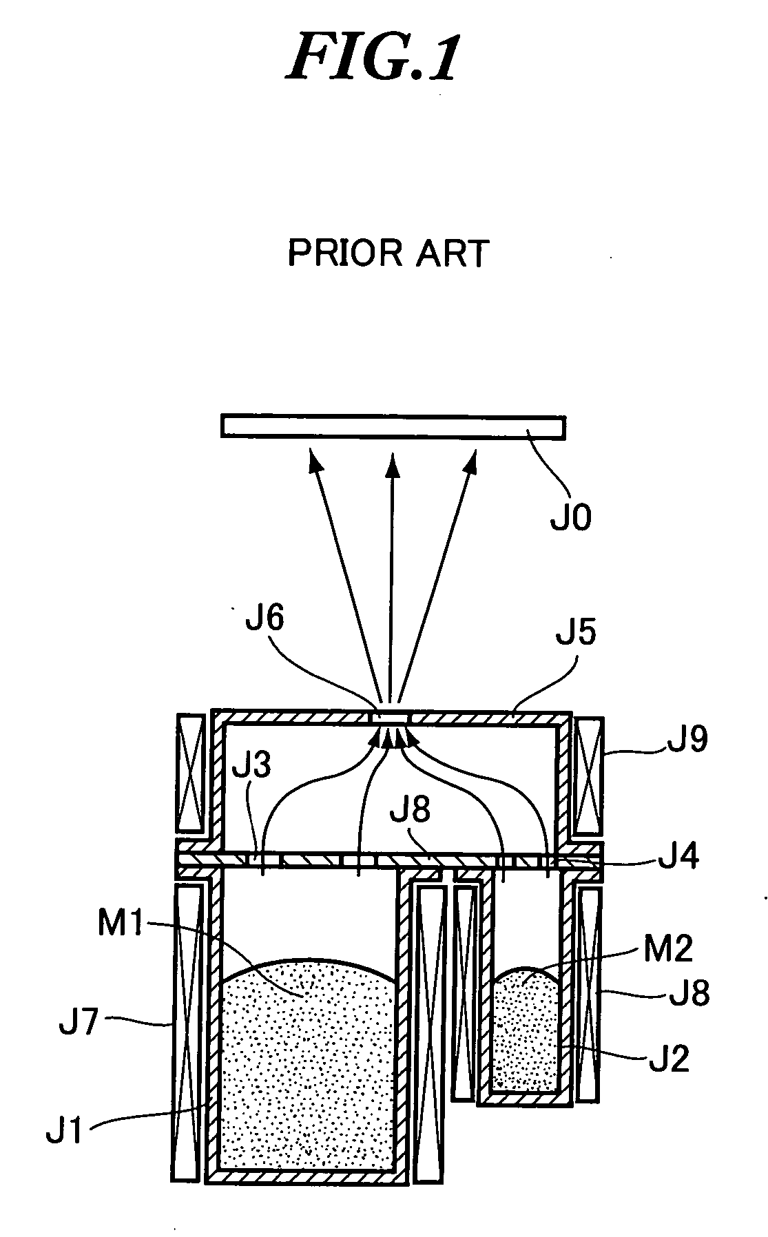
However, the above-discussed prior art has been confronted with a problem that the film formation material M1 diffuses and thus invades from the mixing chamber J5 to the crucible J2, resulting in an undesired mixing of the film formation material M1 with the film formation material M2 and a clogging of the inlet J3 or J4.
This however can cause a problem that the film formation material M2 (or M1) will be overheated and thus deteriorates the film formation material.
Moreover, when manufacturing an organic EL panel, if a shadow mask is employed to perform a discriminated painting using different film formation materials having different luminescent colors, the aforementioned positional deviation among film formation areas will cause some color deviations, rendering it impossible to perform film formations of appropriate colors in desired film formation areas.

Method used


Image

  • Film formation source, vacuum film formation apparatus, and method of manufacturing organic EL panel
  • Film formation source, vacuum film formation apparatus, and method of manufacturing organic EL panel
  • Film formation source, vacuum film formation apparatus, and method of manufacturing organic EL panel

Examples


Embodiment Construction

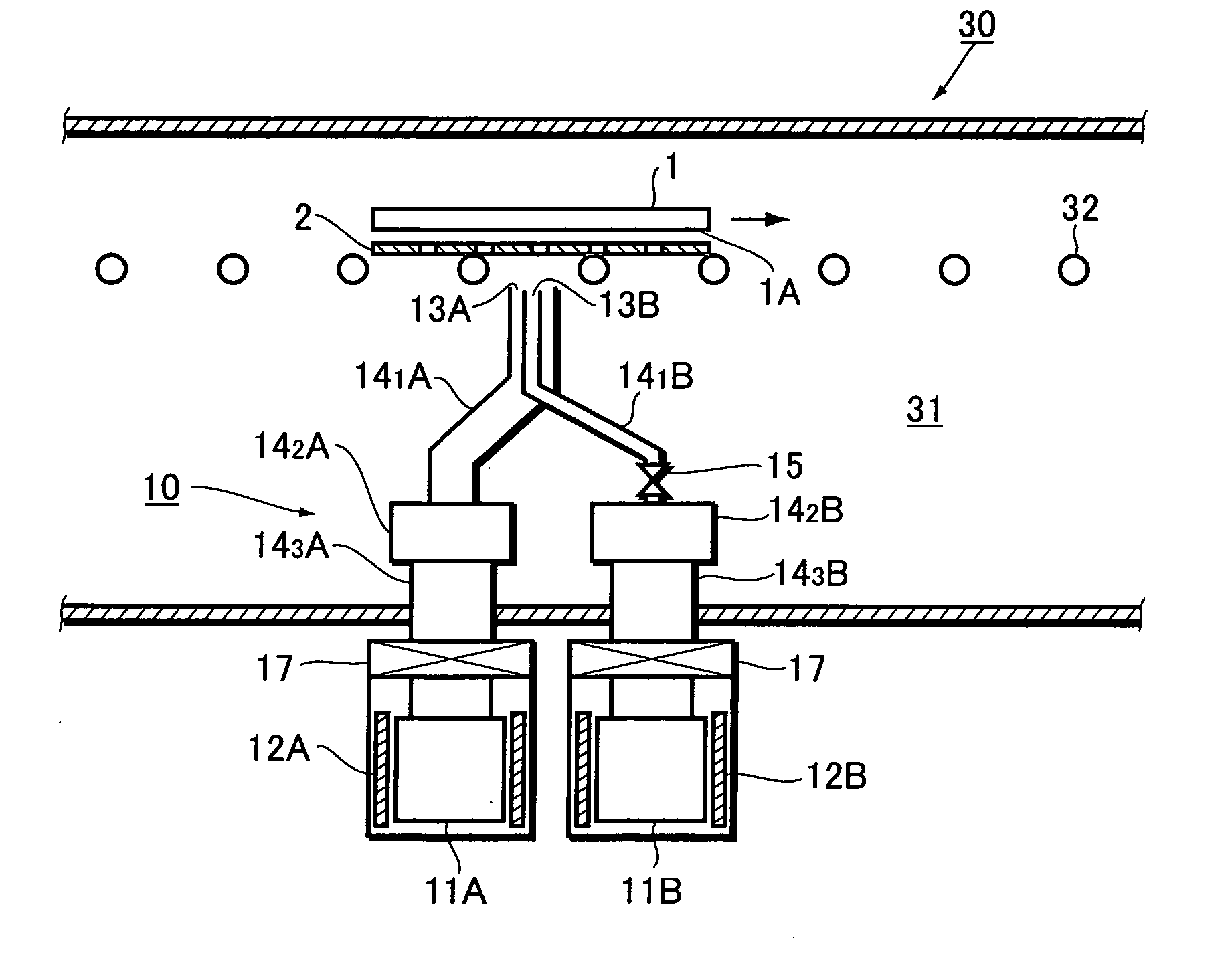
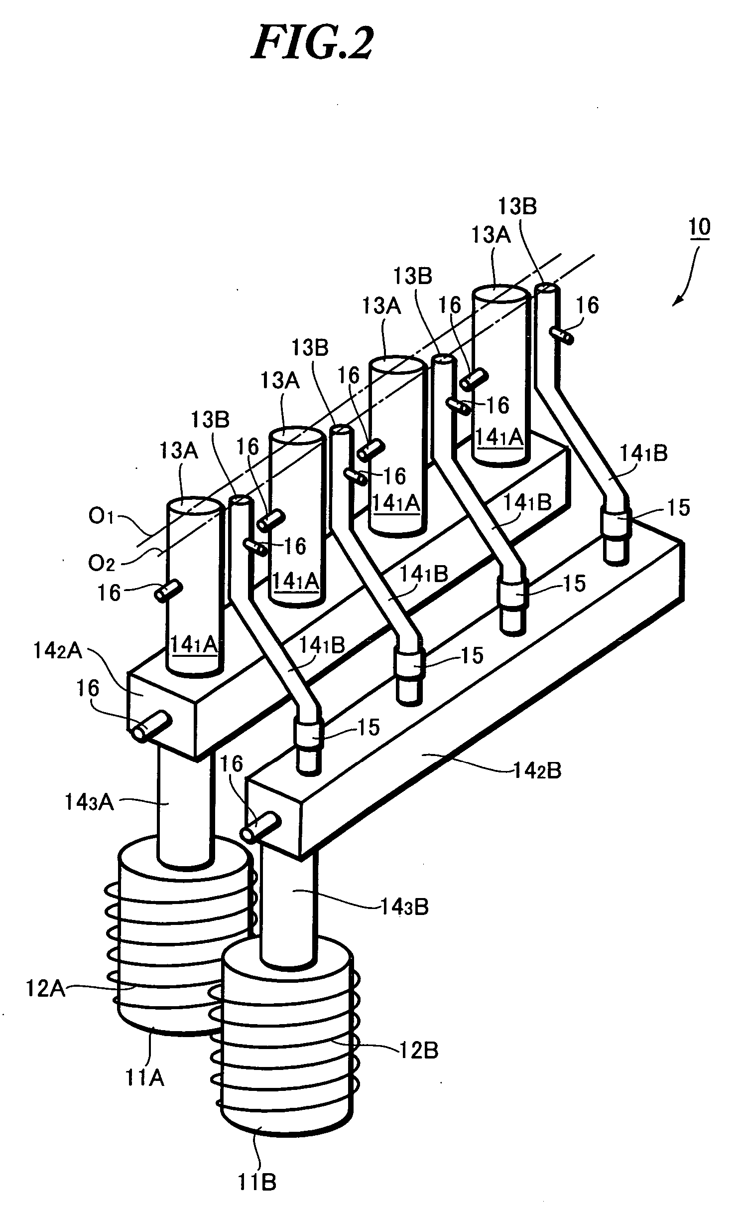
[0030] Preferred embodiments of the present invention will be described below with reference to the accompanying drawings. FIG. 2 is an explanatory view showing a film formation source for use in a vacuum film formation apparatus according to one embodiment of the present invention. In fact, the film formation source 10 is formed to heat and thus sublimate or evaporate several different sorts of film formation materials so as to produce a plurality of atom flows or molecule flows of different film formation materials and to emit the same to a common film formation surface to form films of the film formation materials on the film formation surface. Here, although the illustrated example only shows two film formation materials mixed together, the present invention also includes mixing three or more different film formation materials to perform desired film formation.

[0031] As shown, the film formation source 10 comprises a plurality of material accommodating units 11A and 11B contain...


PUM

PropertyMeasurementUnit
outer diametersaaaaaaaaaa
luminescentaaaaaaaaaa
colorsaaaaaaaaaa

Abstract

It is an object of the present invention to easily adjust the percentage of each component when mixing together several film formation materials, so as to prevent deviation among film formation areas. A film formation source of a vacuum film formation apparatus comprises: a plurality of material accommodating units containing a plurality of film formation materials; a plurality of heating means for heating the film formation materials contained within the material accommodating units; a plurality of discharge outlets for discharging atom flows or molecule flows of film formation materials; a plurality of discharge passages for air-tightly communicating the material accommodating units with discharge outlets. Two groups of discharge outlets each for discharging an identical film formation material are arranged in one direction, in a manner such that two elongated discharge areas formed by linearly connecting the outer edges of the discharge outlets are at least partially overlapped with each other when viewed from overhead.

Description

BACKGROUND OF THE INVENTION [0001] The present invention relates to a film formation source, a vacuum film formation apparatus, and a method of manufacturing an organic EL panel. [0002] The present application claims priority from Japanese Application No. 2004-243298, the disclosure of which is incorporated herein by reference. [0003] As a technique which forms a thin film on a substrate, there has been known a vacuum film formation (such as vacuum vapor deposition and molecular beam epitaxy). In vacuum vapor deposition, a film formation material is heated and thus sublimated or evaporated to generate an atom flow or molecule flow of the film formation material which is then emitted to a film formation surface of a substrate disposed within a vacuum film formation room (vacuum chamber), thereby allowing the film formation material to adhere to the film formation surface and thus forming a thin film thereon. Usually, a vacuum film formation apparatus which performs such a vacuum film...

Claims


Application Information

Patent Timeline
Patent Type & Authority Applications(United States)
IPC IPC(8): B05D5/06C23C16/00
CPCC23C14/243C23C14/12H10K71/164
Inventor ABIKO, HIROSIMASUDA, DAISUKEUMETSU, SHIGEHIRO
Owner TOHOKU PIONEER CORP
Learn More