
Automatic focusing system

a focusing system and automatic technology, applied in the field of automatic focusing system, can solve problems such as failure to correctly perform focusing

Inactive Publication Date: 2006-03-02
FUJI PHOTO OPTICAL CO LTD
View PDF15 Cites 18 Cited by
  • Summary
  • Abstract
  • Description
  • Claims
  • Application Information

AI Technical Summary

Benefits of technology

[0009] In view of the above-described circumstances, an object of the present invention is to provide an automatic focusing system in which the quantities of subject light incident on a plurality of image pickup surfaces of an AF image pickup device are in a fixed quantity ratio irrespective of whether or not the subject light before splitting into the quantities of light incident on the image pickup surfaces is polarized, and which is capable of accurately performing automatic focusing.
[0011] In an automatic focusing system according to a second aspect of the present invention, the conversion device in the first aspect of the present invention is a ¼ wavelength plate. For example, linearly polarized subject light is converted into circularly polarized light by the ¼ wavelength plate to eliminate the polarity of the subject light.
[0013] In the automatic focusing system in accordance with the present invention, the quantities of subject light incident on the plurality of image pickup surfaces of the AF image pickup device are in a fixed quantity ratio at all times and, therefore, automatic focusing can be performed with accuracy.

Problems solved by technology

There is also a possibility of subject light itself entering the picture taking lens being polarized, even if the polarizing effect of the optical system is low.
However, if a half mirror or a prism is used as the light splitting optical system for splitting subject light introduced into the AF optical path for imaging on the image pickup surfaces of the AF image pickup devices, a problem described below arises.
Therefore, when polarized subject light such as that described above enters the light splitting optical system, the quantities of light incident on the image pickup surfaces of the AF image pickup devices are not in the quantity ratio determined in advance, resulting in failure to correctly perform focusing.

Method used


Image

  • Automatic focusing system
  • Automatic focusing system
  • Automatic focusing system

Examples


Embodiment Construction

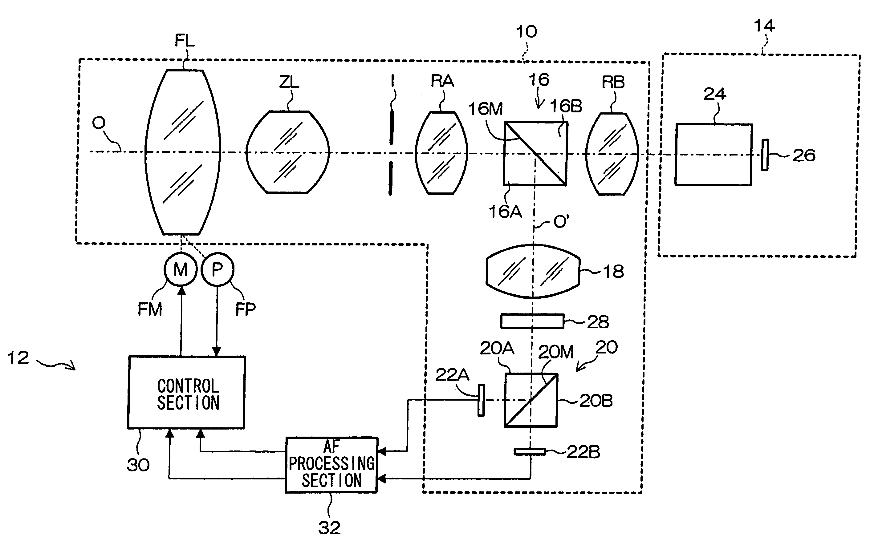
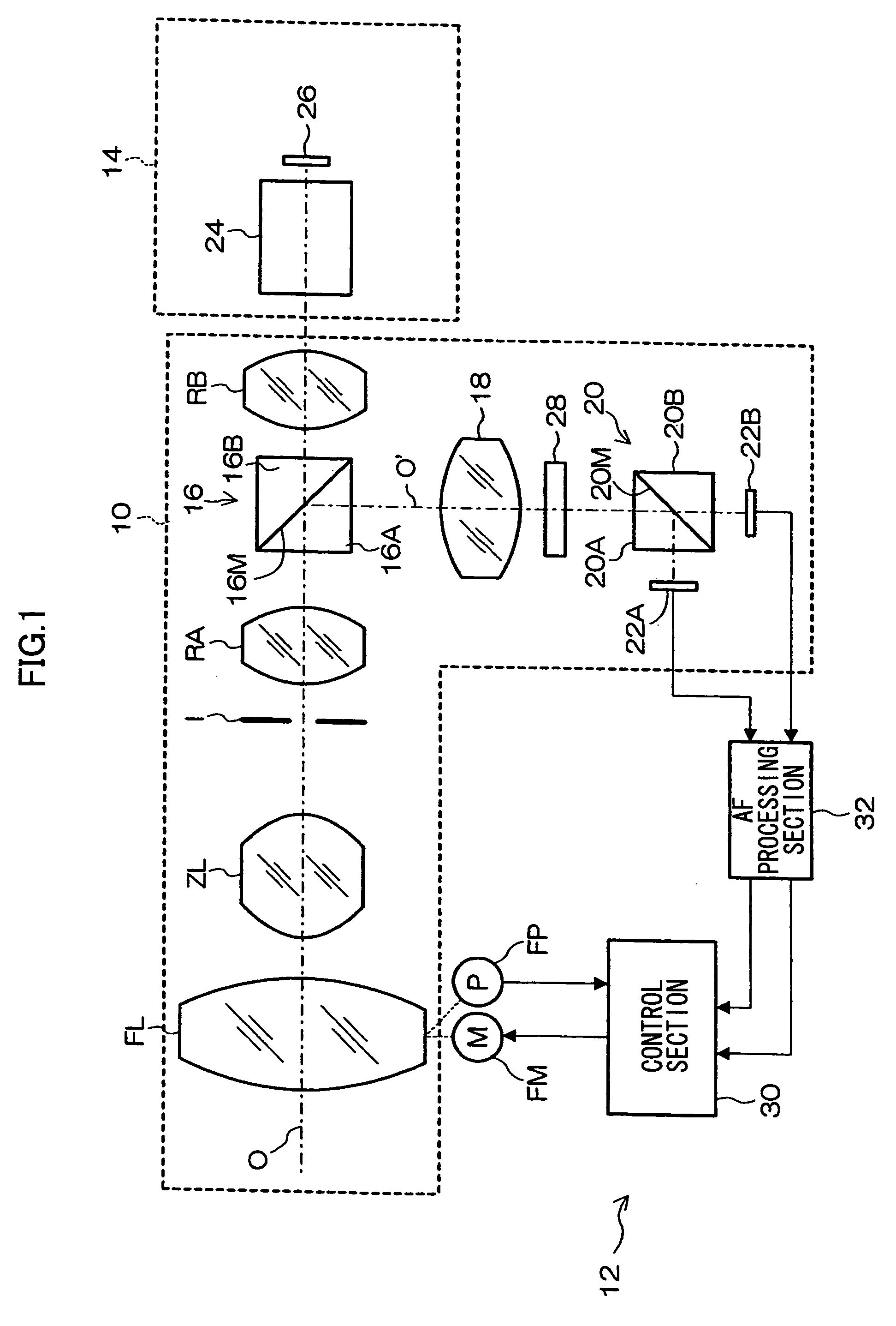
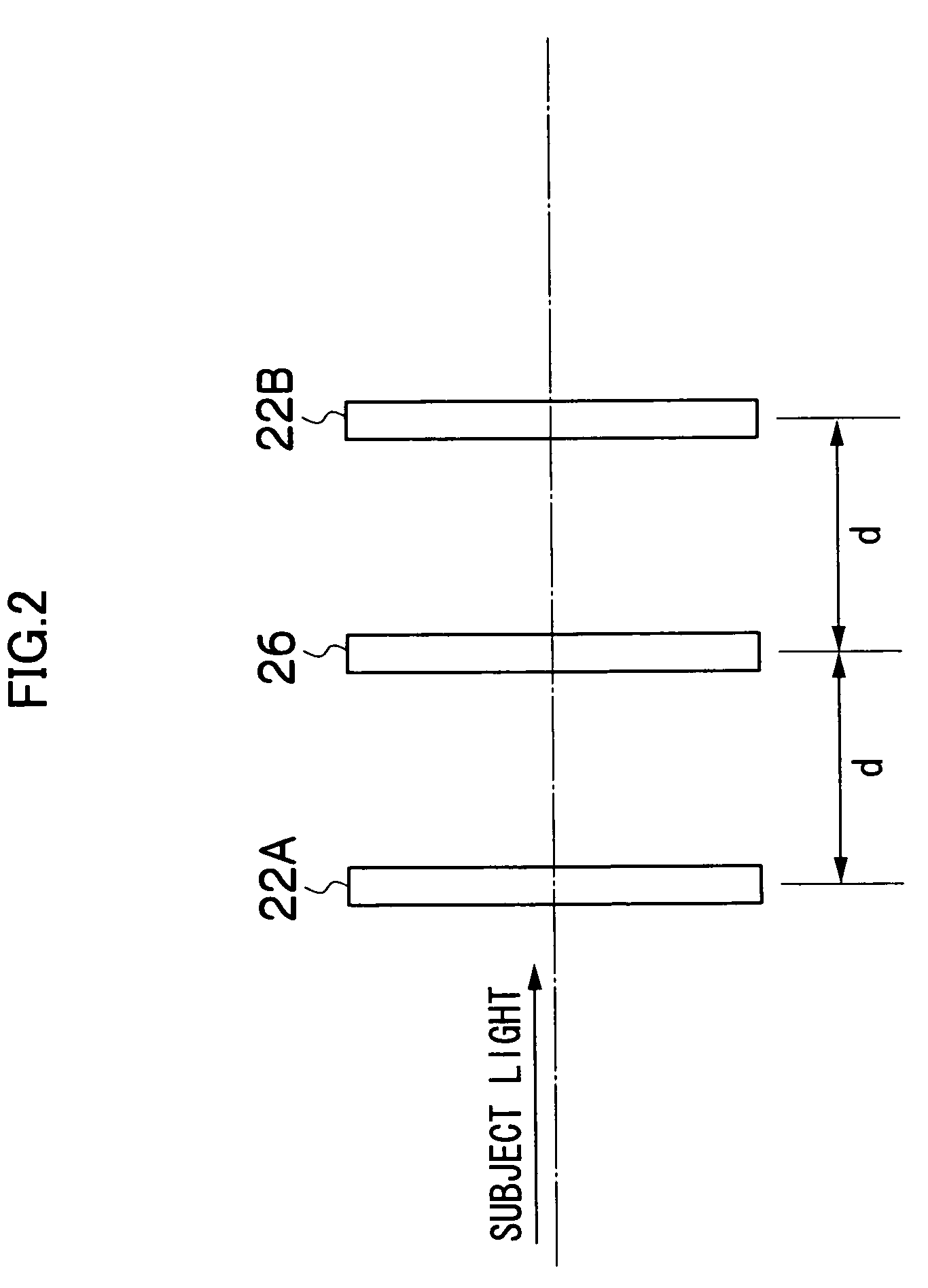
[0019] A preferred embodiment of an automatic focusing system in accordance with the present invention will be described with reference to the accompanying drawings.

[0020]FIG. 1 is a block diagram showing the construction of a lens system to which an automatic focusing system in accordance with the present invention is applied. The system shown in FIG. 1 is constituted by, for example, a picture taking lens 10 (optical system) attached by means of a mount on a camera body 14 (camera head) of a broadcasting television camera, and a control system 12 which controls picture taking lens 10. The apparatus constituting the system may take a form freely selected, e.g., one in which the picture taking lens 10 and the control system 12 are combined integrally with each other except for a certain portion to form a lens unit, or one in which the picture taking lens 10 and the control system 12 are constructed as separate units.

[0021] In the picture taking lens 10, a focusing lens (group) FL,...


PUM


Abstract

An automatic focusing system comprising: a plurality of image pickup surfaces of an AF image pickup device for taking images of a subject for performing automatic focusing of a picture taking lens, the image pickup surfaces being placed at such positions that the length of optical paths to the image pickup surfaces differ from each other; a common optical path which is a portion of an optical path through which subject light entering the picture taking lens are supplied to the plurality of image pickup surfaces, and through which the entire subject light to be incident on the image pickup surfaces passes; a light splitting device which splits the subject light supplied through the common optical path into subject lights respectively incident on the plurality of image pickup surfaces; a focusing control device which controls focusing of the picture taking lens on the basis of contrasts in the subject images obtained through the plurality of image pickup surfaces so that a correct focus on the subject is achieved; and a conversion device which is placed at a predetermined position in the common optical path, and which converts the subject light reaching the predetermined position into non-polarized light if the subject light is polarized light, and makes the converted subject light enter the light splitting device.

Description

BACKGROUND OF THE INVENTION [0001] 1. Field of the Invention [0002] The present invention relates to an automatic focusing system and, more particularly, to an automatic focusing system using automatic focusing based on an optical path length difference method of automatically performing focusing on the basis of contrasts in images of a subject imaged on a plurality of image pickup surfaces with optical path length differences. [0003] 2. Related Art [0004] An automatic focusing (AF) method called an optical path length difference method has been proposed as an AF method suitable for video cameras such as television cameras for broadcasting (see, for example, Japanese Patent Application Laid Open No. 2002-365517). In an AF system using AF based on the optical path length difference method, a light splitting optical system such as a half mirror is placed in a picture taking lens to form an AF optical path branching from the main optical path, and part of subject light entering the pic...

Claims


Application Information

Patent Timeline
IPC IPC(8): H04N5/232
CPCH04N5/23212G02B7/38H04N23/673
Inventor KUWAKINO, KOSHI
Owner FUJI PHOTO OPTICAL CO LTD
Learn More