
Vibration prevention structure in engine

a technology of vibration prevention and engine, which is applied in the direction of machines/engines, mechanical equipment, cylinders, etc., can solve the problems of large possibility of torsional vibration generation of crankshaft propellers on one end, and inability to perform easy operation, so as to enhance the vibration prevention property of crankshaft and minimize the effect of the vibration suppressor

Inactive Publication Date: 2006-03-02
HONDA MOTOR CO LTD
View PDF2 Cites 11 Cited by
  • Summary
  • Abstract
  • Description
  • Claims
  • Application Information

AI Technical Summary

Benefits of technology

[0006] Since the vibration suppressor is mounted on the end portion of the crankshaft opposite to the propeller, it is possible to effectively reduce the vibrations on the end portion of the crankshaft opposite to the propeller. Further, since the pair of vibration pendulum type weights provided to the vibration suppressor are arranged outside the crankcase, at the time of changing the vibration suppressor in conformity with a properties of the propeller, it is unnecessary to perform a large-scale operation such as dissembling of the crankcase or the like whereby the vibration suppressor can be easily changed thus facilitating the inspection and the maintenance.
[0008] By supporting a shaft end of the crankshaft opposite to the propeller while protecting the vibration suppressor, it is possible to obtain the more excellent vibration reduction effect.
[0009] The invention may also include on the crankcase, a detachably mounted cover which integrally includes a pump mounting portion for mounting a pump housing which is provided to a water pump driven by the crankshaft, and the vibration suppressor is covered with the crankcase and the cover. It is possible to protect vibration suppressor by reducing the number of parts.
[0011] The removal prevention member which prevents the removal of the pin from the support arm portion is detachably mounted on the support arm portion and hence, the exchange of pins having different outer diameters which becomes necessary to change the order of vibration or the like is facilitated whereby it is possible to miniaturize the vibration suppressor by arranging both weights on a same rotating surface.
[0012] Further, the orders of vibration of both weights may be set different from each other. By allowing the pair of weights to have the orders of vibration different from each other, it is possible to further enhance the vibration prevention property of the crankshaft.

Problems solved by technology

Here, as disclosed in the above-mentioned JP-A-2002-213302, the crankshaft which mounts the propeller on one end thereof has a large possibility of generating torsional vibrations.
In applying such vibration prevention structure to the crankshaft which mounts the propeller on one end thereof, the vibration reduction effect on an end portion of the crankshaft opposite to the propeller is small and, at the same time, with respect to an operation which is performed at the time of changing the vibration suppression structure in conformity with properties of the propeller, a large-scale operation such as dissembling of the crank case or the like becomes necessary and such an operation can not be performed easily.

Method used


Image

  • Vibration prevention structure in engine
  • Vibration prevention structure in engine
  • Vibration prevention structure in engine

Examples


Embodiment Construction

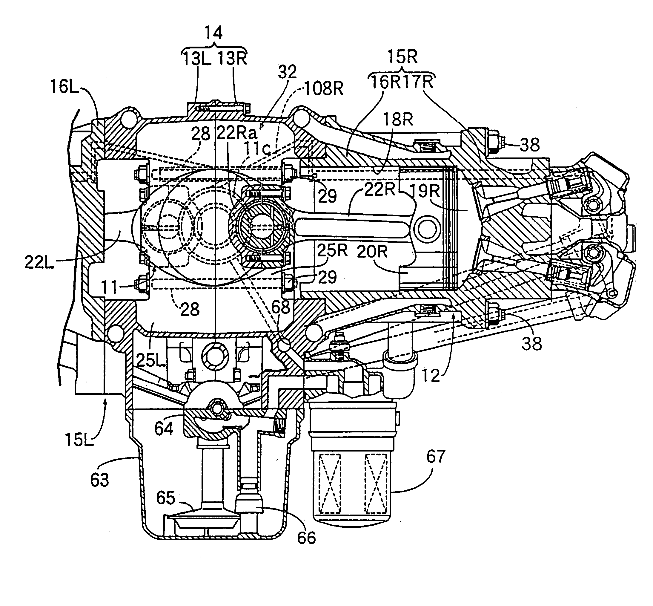
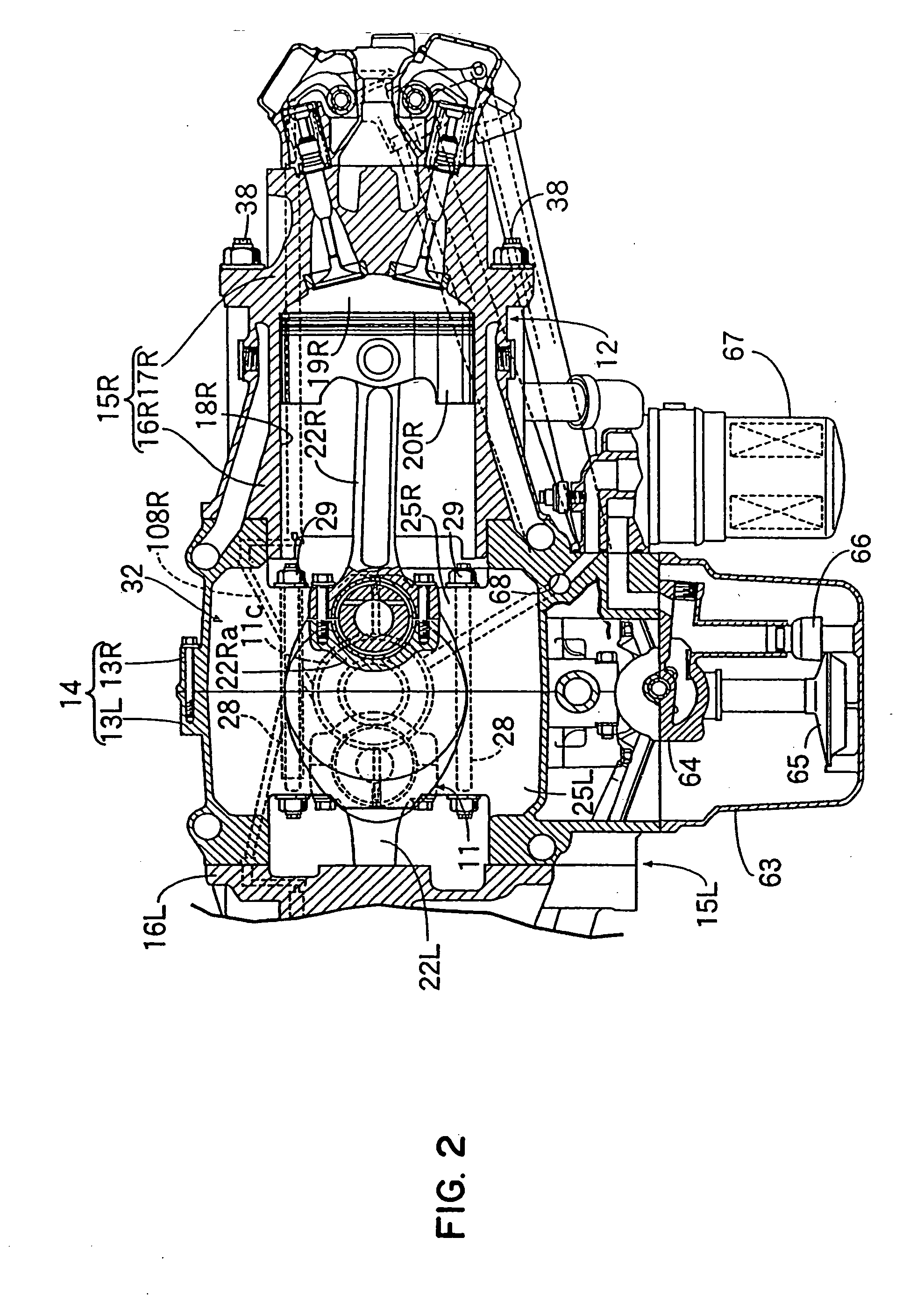
[0019] In FIG. 1 and FIG. 2, a 4-cycle horizontal-opposed-type 4-cylinder engine is mounted on an airplane, for example, wherein the engine is housed in the inside of a front cowl of a body of the air plane in a state that an axis of a crankshaft 11 is arranged along the fore-and-aft direction, and a spinner having a plurality of propellers is coaxially coupled to the crankshaft 11.

[0020] An engine body 12 of the engine includes a crankcase 14 which is formed by joining a left case half body 13L which is arranged on a left side when the engine is viewed from a rear side and a right case half body 13R which is arranged on a right side when the engine is viewed from the rear side, and left and right cylinder blocks 15L, 15R which are respectively arranged on left and right sides of the crankcase 14.

[0021] The left cylinder block 15L is constituted by integrally forming a left cylinder barrel 16L and a left cylinder head 17L, the right cylinder block 15R is constituted by integrally ...


PUM


Abstract

In an engine having a propeller mounted on one end of a crankshaft, the vibrations on an end portion of the crankshaft opposite to the propeller are effectively suppressed with a pair of vibration pendulum type weights arranged outside the crankcase whereby it is possible to easily perform a change of the vibration suppression structure in conformity with the property of the propeller.

Description

FIELD OF THE INVENTION [0001] The present invention relates to an engine in which at least two bearing portions which rotatably support at least a pair of crank journals provided to a crankshaft are mounted on a crankcase, both ends of the crankshaft are projected from the outermost bearing portions which are arranged along an axis of the crankshaft out of the respective bearing portions, and a propeller is mounted on one end of the crankshaft, and more particularly to improvement of the vibration prevention structure for suppressing the vibrations of a crankshaft. BACKGROUND OF THE INVENTION [0002] An engine for an air plane which mounts a propeller on one end of a crankshaft is known by JP-A-2002-213302, and a vibration prevention structure which suppresses the vibrations of a crankshaft is disclosed in JP-A-2003-293701. [0003] Here, as disclosed in the above-mentioned JP-A-2002-213302, the crankshaft which mounts the propeller on one end thereof has a large possibility of generat...

Claims


Application Information

Patent Timeline
Patent Type & Authority Applications(United States)
IPC IPC(8): F02F7/00
CPCF02F2007/0075F16F15/26Y10T74/2128F02B75/243F02B75/06
Inventor SANADA, MAKOTOSUZUKI, TATSUOKUBO, KATSUHIRO
Owner HONDA MOTOR CO LTD
Learn More