
Method of detecting and analyzing changes in the external loading conditions of a structure

a technology of external loading and analysis method, which is applied in the direction of instruments, force/torque/work measurement, instruments, etc., can solve the problems of difficult handling, laborious and time-consuming, and difficult to secure such large numbers of wires, so as to facilitate the detection of load changes

Active Publication Date: 2006-03-02
ACELLENT TECH
View PDF39 Cites 21 Cited by
  • Summary
  • Abstract
  • Description
  • Claims
  • Application Information

AI Technical Summary

Benefits of technology

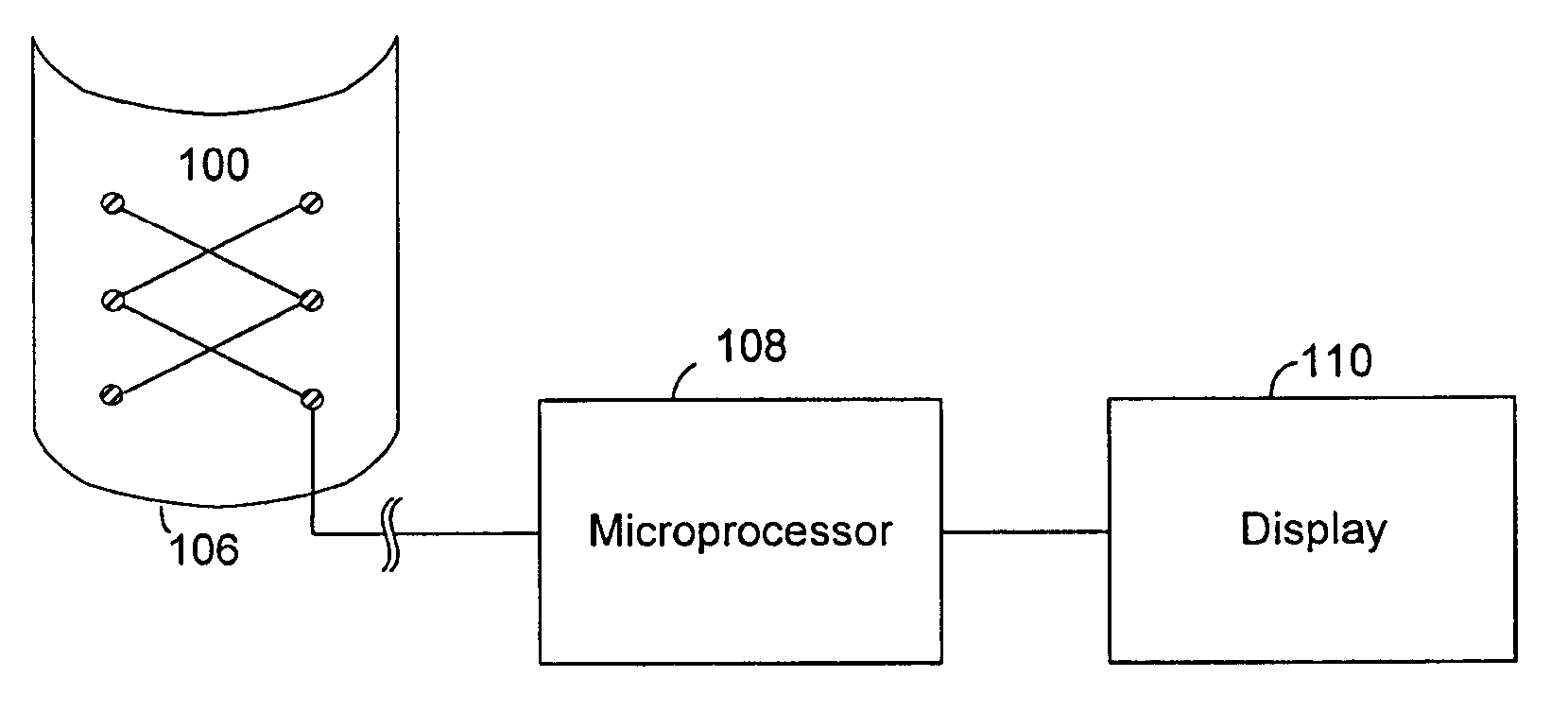
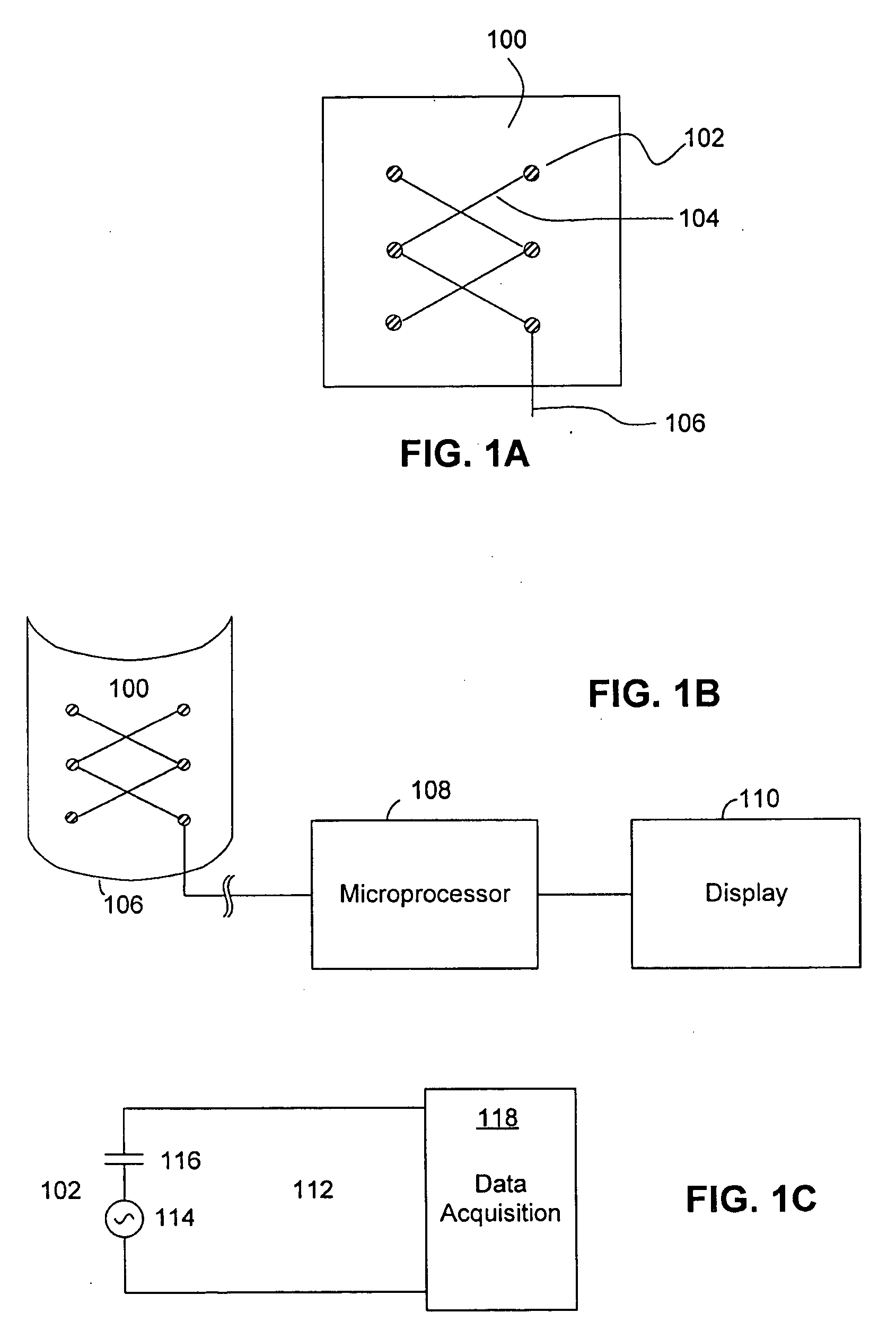
The present invention provides a method for detecting and analyzing changes in the external loading condition of a structure using a flexible substrate with sensors attached to it. The sensors generate electrical signals when they detect stress waves caused by a load change on the structure. These signals are then analyzed to determine the location and severity of the load change. This method allows for early detection and timely response to load changes, which can help to prevent damage and improve the overall performance of the structure.

Problems solved by technology

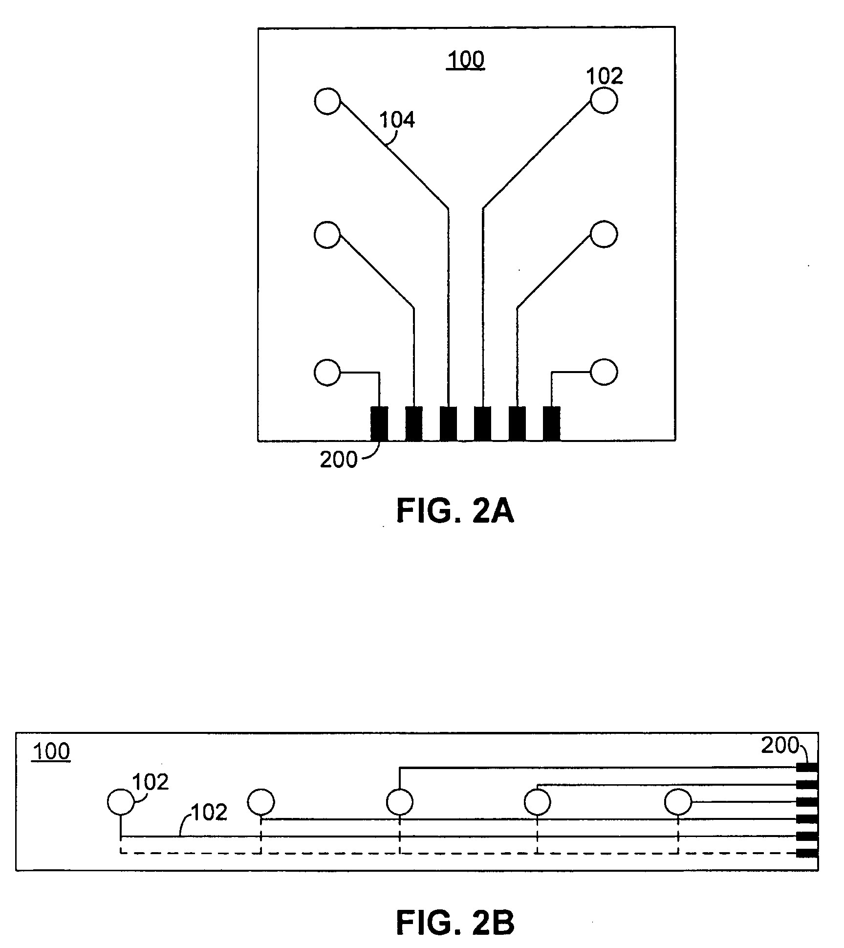
The technical problem addressed in this patent is the difficulty of placing large numbers of sensing elements in structures, such as those used for structural health monitoring. The invention proposes a solution by employing a flexible substrate with a distributed network of sensors built in or attached to it, which can detect and analyze changes in external loading conditions of a structure. The invention aims to provide a more efficient and cost-effective way of detecting and analyzing load changes in structures, which can help reduce the time and expense associated with inspection and maintenance.

Method used


Image

  • Method of detecting and analyzing changes in the external loading conditions of a structure
  • Method of detecting and analyzing changes in the external loading conditions of a structure
  • Method of detecting and analyzing changes in the external loading conditions of a structure

Examples


Embodiment Construction

[0019] In one embodiment of the invention, a flexible layer with sensors distributed thereon is attached on or within a structure. As the sensors are distributed across the flexible layer, the layer effectively creates a network of sensors that are spread across various sites on the structure. When the sensors detect a change in the external loading condition of the structure, their resulting electrical signals are analyzed to determine various characteristics of the change. For example, because the sensors are spread out along various locations on the structure, they will each experience different stress waves, at different times. Analysis of the characteristics of each can reveal the location and severity of the change in load condition. Similarly, if the sensor signals are filtered to screen out various frequencies, the sensors are effectively tuned to ignore certain types of changes, such as impacts that are known to be of no concern. Accordingly, different responses can be init...


PUM


Abstract

A method for both detecting and analyzing a change in the loading condition of a structure. A flexible substrate is employed, in which a distributed network of sensors is built. This substrate is either affixed to the surface of the structure, or built within it, so as to be able to detect propagating stress waves. After load change is detected, the resulting sensor signals are analyzed to determine the location, severity, and/or any characteristic frequencies of the load change. This information is then used to determine an appropriate response.

Description


Claims


Application Information

Patent Timeline
Owner ACELLENT TECH
Learn More