
Introducer assembly with suspended seal

Inactive Publication Date: 2006-02-23
TYCO HEALTHCARE GRP LP
View PDF45 Cites 83 Cited by
  • Summary
  • Abstract
  • Description
  • Claims
  • Application Information

AI Technical Summary

Benefits of technology

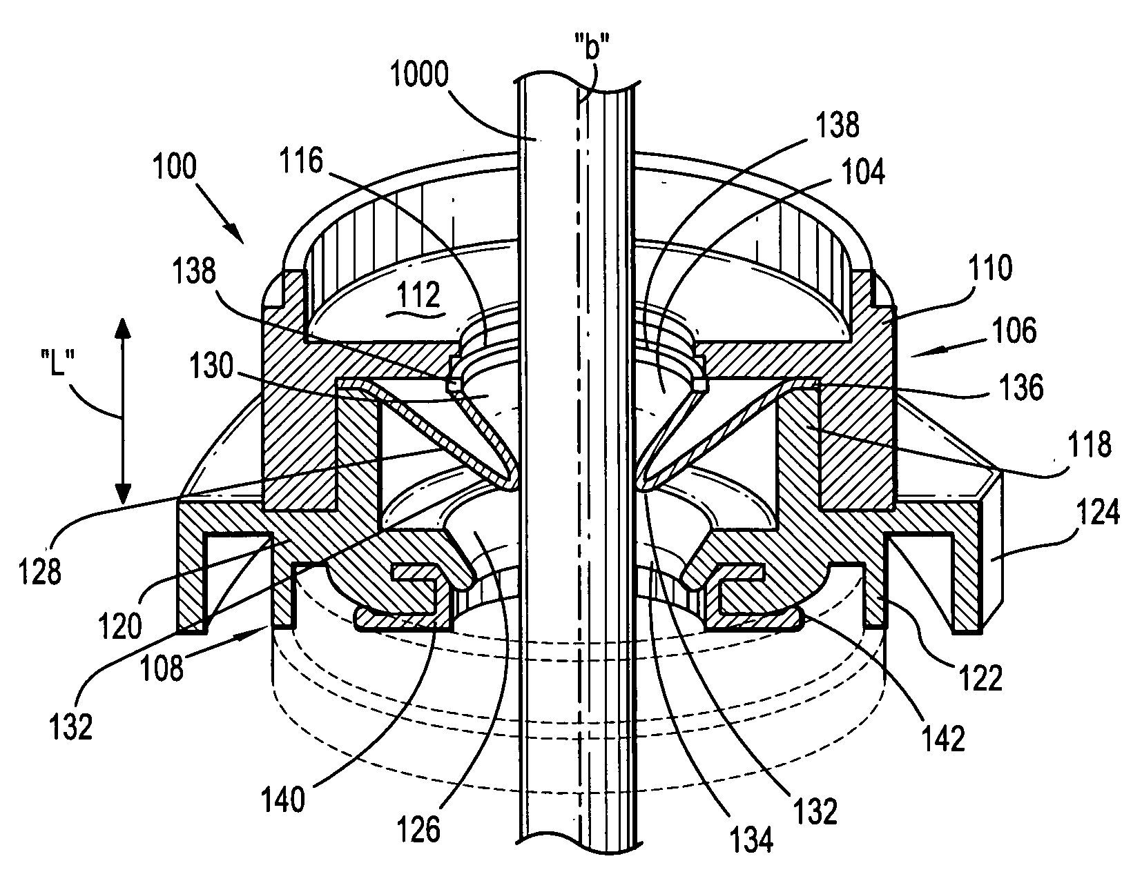
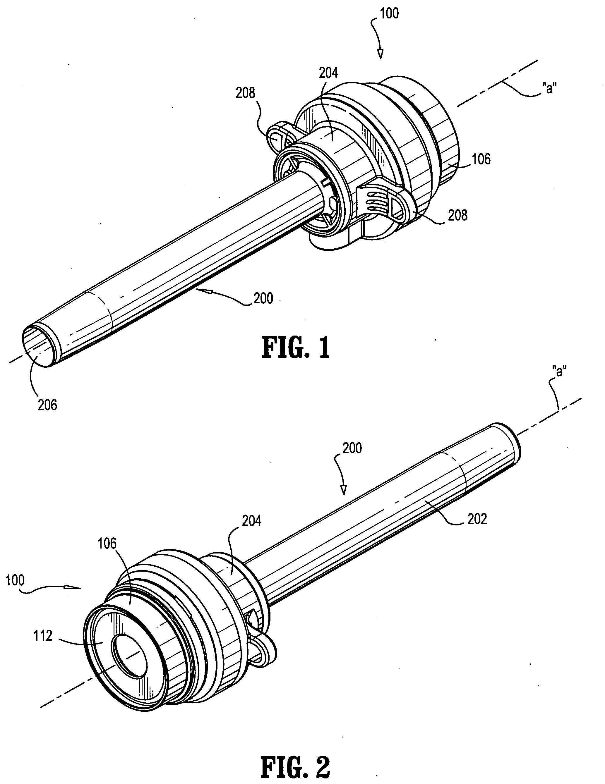
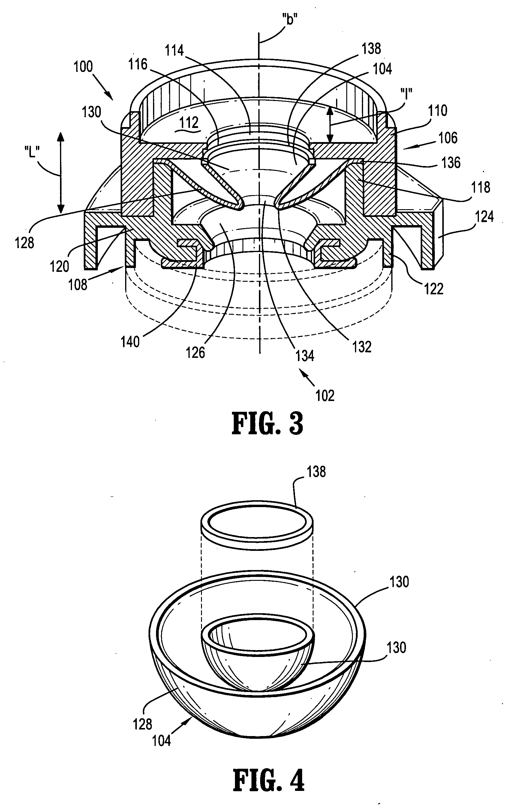
[0006] Accordingly, the present disclosure provides a seal assembly for an access apparatus, which will allow a surgeon to efficaciously utilize instruments of varying diameter in a surgical procedure. This seal assembly obviates the need for multiple adapters to accommodate instruments of varying diameters by providing a resilient seal member which is mounted in a suspended manner to thereby facilitate insertion and withdrawal of the instrument within an aperture of the seal member.
[0008] In one preferred embodiment, the proximal seal end of the seal member is disposed radially inwardly of the distal seal end. The distal seal end is connected to the access member along an outer periphery of the distal seal end. Preferably, the proximal seal end defines an outer periphery and an annular member mounted adjacent the outer periphery. The annular member defines a dimension greater than a corresponding dimension of the longitudinal opening of the access member to minimize inversion of the seal member upon withdrawal of the surgical instrument from the seal member.
[0013] The proximal seal end may include an annular element associated with the outer periphery thereof. The annular element is preferably less compliant than remaining portions of the inner area of the seal member. The cannula housing may include a transverse wall defining an aperture in general alignment with the axis of the cannula sleeve and being disposed proximal of the seal member. The annular element defines a transverse dimension greater than a corresponding transverse dimension of the aperture of the cannula housing such that the annular element is retained distal of the transverse wall during insertion and withdrawal of the surgical instrument thereby minimizing inversion of the seal member.

Problems solved by technology

A difficulty encountered with conventional seal assemblies, however, is the inability of accommodating the wide range of sizes of instrumentation.
In addition, manipulation of instrumentation within the cannula often presents difficulties with respect to maintaining seal integrity.

Method used


Image

  • Introducer assembly with suspended seal
  • Introducer assembly with suspended seal
  • Introducer assembly with suspended seal

Examples


Embodiment Construction

[0027] The seal assembly of the present disclosure, either alone or in combination with a seal system internal to a cannula assembly, provides a substantial seal between a body cavity of a patient and the outside atmosphere before, during and after insertion of an instrument through the cannula assembly. Moreover, the seal assembly of the present disclosure is capable of accommodating instruments of varying diameters, e.g., from 5 mm to 15 mm, by providing a gas tight seal with each instrument when inserted. The flexibility of the present seal assembly facilitates endoscopic surgery where a variety of instruments having different diameters are often needed during a single surgical procedure.

[0028] The seal assembly contemplates the introduction and manipulation of various types of instrumentation adapted for insertion through a trocar and / or cannula assembly while maintaining a fluid tight interface about the instrumentation to preserve the atmospheric integrity of a surgical proce...


PUM


Abstract

A surgical access apparatus includes an access member dimensioned for insertion within tissue and having a longitudinal opening to permit introduction of a surgical object through the access member to perform a procedure on underlying tissue. A seal member is mounted across the longitudinal opening of the access member and has an internal portion defining an aperture for forming a substantial seal about the surgical object introduced through the longitudinal opening of the access member. The seal member includes a first seal portion extending from the internal portion and being mounted in suspended relation to the access member, and a second seal portion extending from the internal portion and disposed radially outward of the first seal portion, and being attached to the access member

Description

CROSS REFERENCE TO RELATED APPLICATIONS [0001] This application claims priority to U.S. provisional application Ser. No. 60 / 590,176, filed on Jul. 21, 2004, the entire contents of which are incorporated herein by reference.BACKGROUND [0002] 1. Technical Field [0003] The present disclosure relates to a valve system adapted to permit the introduction of surgical instrumentation into a patient's body. In particular, the present disclosure relates to a valve system for use with an access device which is intended for insertion into a patient's body, and to receive an instrument in sealing engagement therewith. [0004] 2. Description of the Related Art [0005] Minimally invasive and laparoscopic procedures generally require that any instrumentation inserted into the body is sealed, i.e., provisions must be made to ensure that gases and / or fluids do not enter or exit the body through an endoscopic incision, such as, for example in surgical procedures where the surgical region is insufflated....

Claims


Application Information

Patent Timeline
IPC IPC(8): A61M5/178
CPCA61B17/3421A61B17/3462A61B17/3498A61M2039/0626A61B2017/3445A61M39/06A61M39/0606A61B2017/3435
Inventor STEARNS, RALPH A.RACENET, DAVID C.STELLON, GENE A.
Owner TYCO HEALTHCARE GRP LP
Learn More