
Continuous flow single sheath for endoscope

a single sheath and endoscope technology, applied in the field of endoscopy, can solve the problems of reducing the capacity of the sheath to deliver and remove liquids, minimizing the diameter, etc., and achieve the effects of reducing the hydraulic diameter, and reducing the size of the sheath

Inactive Publication Date: 2006-02-23
VANCAILLIE THIERRY G
View PDF4 Cites 110 Cited by
  • Summary
  • Abstract
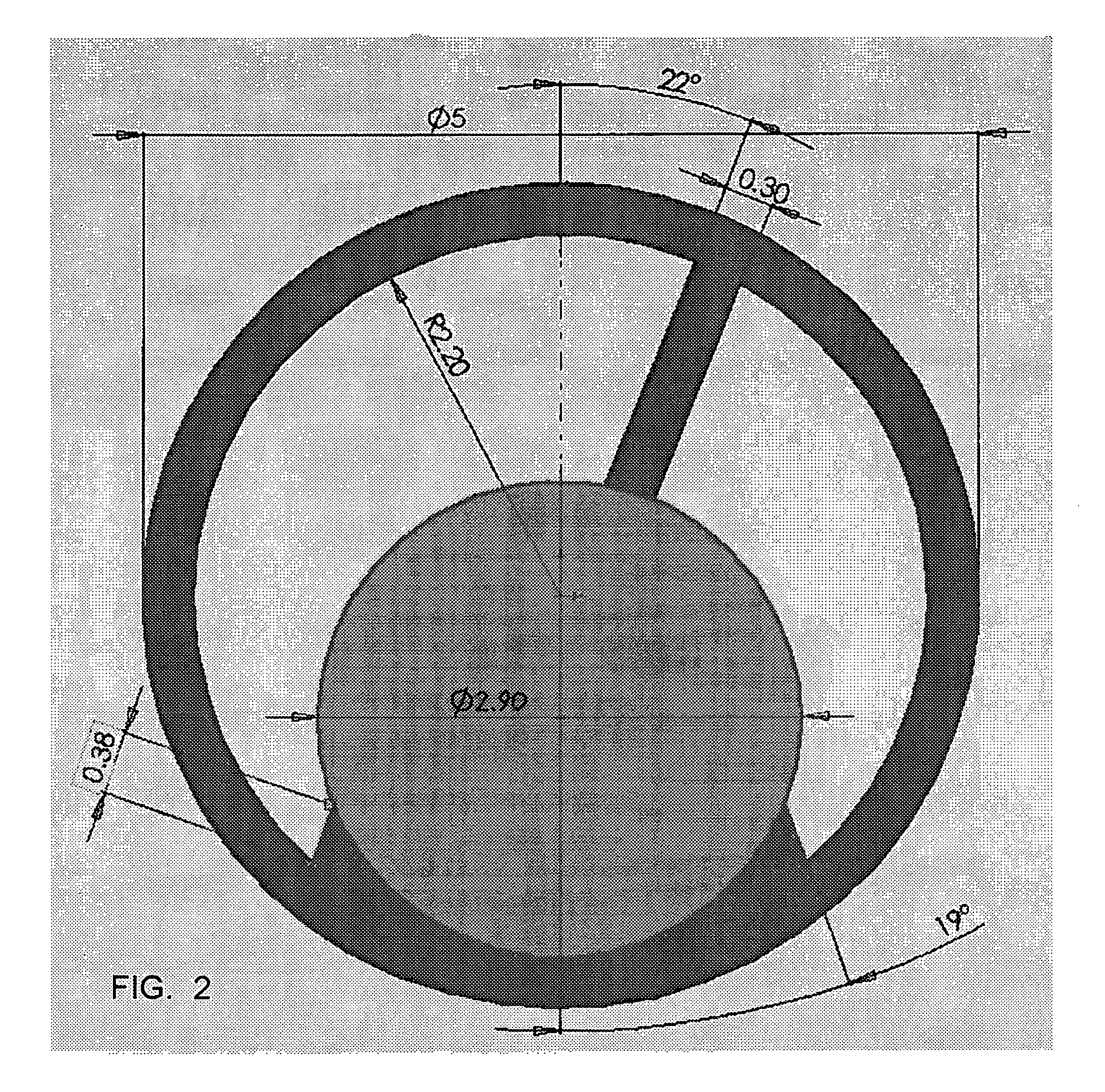
  • Description
  • Claims
  • Application Information

AI Technical Summary

Benefits of technology

[0007] The present invention enables transporting distention medium efficiently through a single sheath surrounding a telescope used for endoscopy in bodily cavities. The invention also provides an automatic flow of medium, while maintaining distention of the cavity to be examined. This is achieved by having a higher hydraulic diameter for the inflow channel as opposed to the outflow channel. This implies that at any given time less fluid will be running out of than into the cavity. The retained fluid distends the cavity to be examined until resistance to distention is encountered, which then reduces the inflow and creates an equilibrium between flows. This automatic outflow set-up reduces the need for complicated pump systems and simplifies routine diagnostic procedures.
[0008] A preferred embodiment of a single sheath continuous flow system for endoscopy according to the invention includes a single oval to round tubular structure which conforms to the outside of a telescope, with or without an instrument alongside it. The sheath has internal ridges which, when touching the outside of the telescope, create compartments of unequal hydraulic diameter between the endoscope and the sheath. The inflow area is larger than the outflow area. Under certain circumstances for a passive outflow, a slit is formed along the sheath at a distance from the tip which is introduced in the bodily cavity. This slit is located along the compartment which carries the outflow fluid. This allows a constant leakage of fluid, thus creating a continuous flow of medium through the system of endoscope and cavity. The continuous flow is an advantage as it allows blood and other bodily fluids which obscure the view to be eliminated.
[0009] Among the advantages of the invention are that: reducing the number of sheaths from two to one potentially reduces their diameter; a single sheath system is easier to assemble; unequal compartments allow for automatic distention of bodily cavity; and the structure of the channels increases the hydraulic diameter and thus rheologic properties of the system. These and other advantages of the present invention will become apparent to those skilled in the art upon reading the following detailed description of the preferred embodiments as shown in the several figures of the drawing.

Problems solved by technology

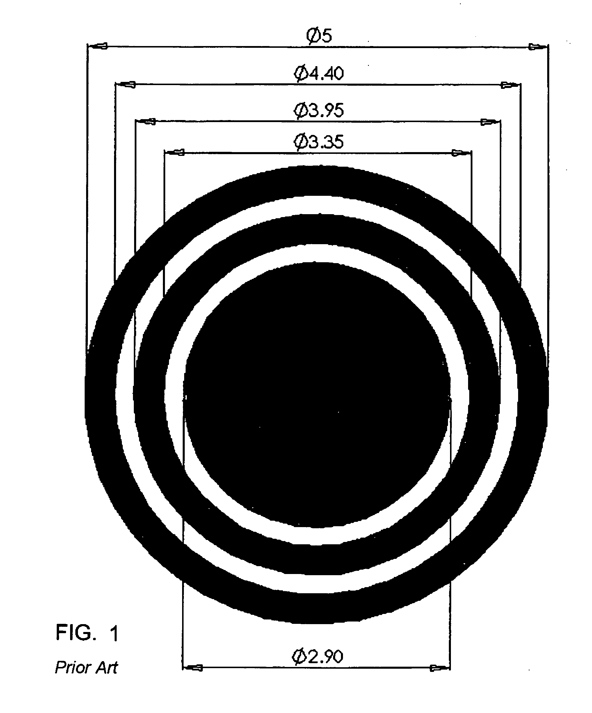
On the other hand minimizing the diameter also reduces the capacity of the sheath to deliver and remove liquids. FIG. 1 is a cross-section of a conventional concentric-channel sheath for a diagnostic probe.

Method used


Image

  • Continuous flow single sheath for endoscope
  • Continuous flow single sheath for endoscope
  • Continuous flow single sheath for endoscope

Examples


Embodiment Construction

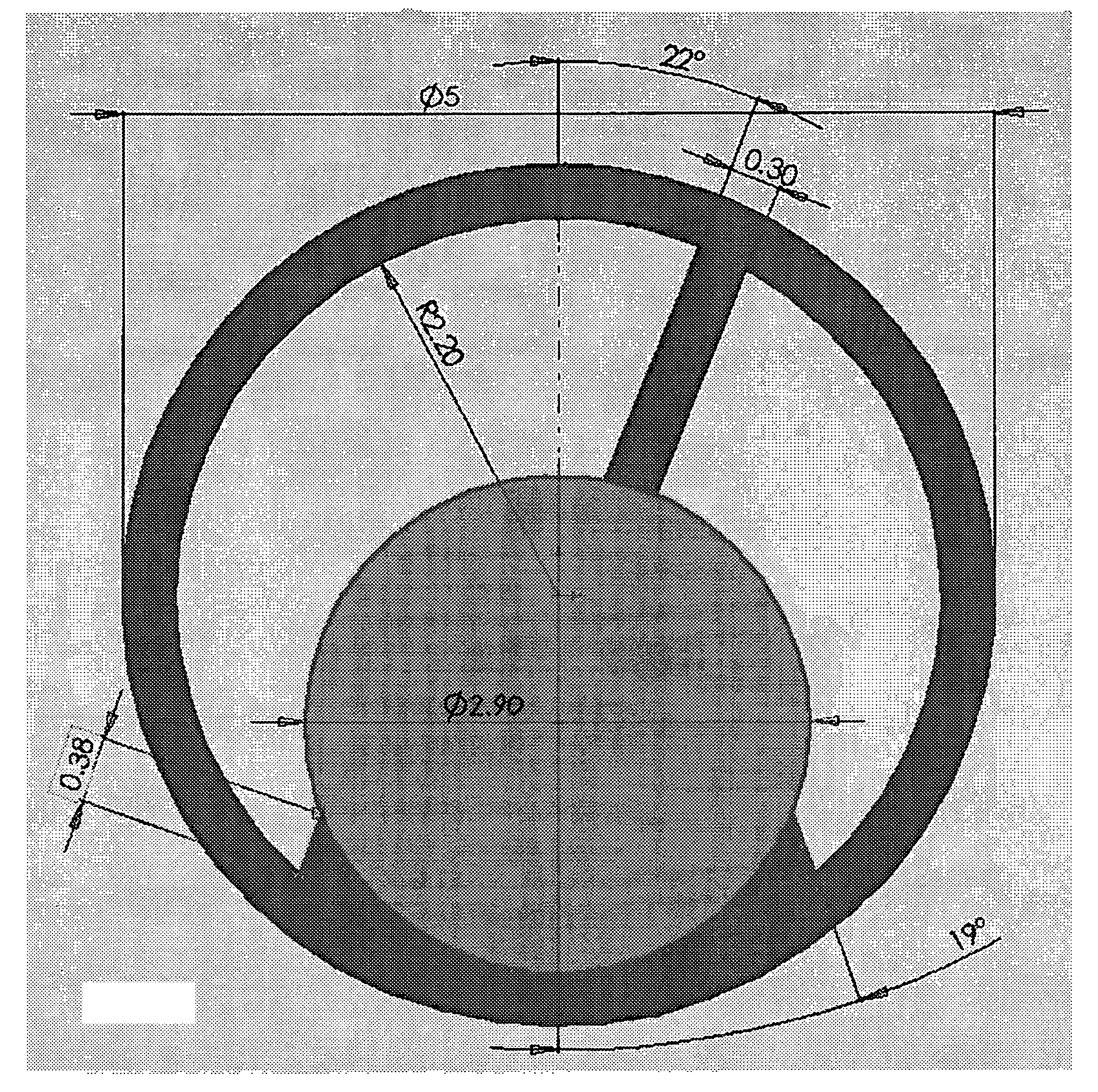
[0018] The present invention uses radial ridges along the inside of a sheath surrounding the telescope. Contact between the ridges and the telescope creates compartments or channels within the sheath, which carry the distention medium. FIG. 2 is a cross-section showing example dimensions of an off-center-channel diagnostic probe according to the invention. The ridges mounted on the inside of the single sheath create two unequal compartments when in contact with the telescope. These compartments are used as channels for in- and out-flow of distention medium. Comparing FIGS. 1 and 2, it is evident that the invention's use of transverse ‘ribs’ increases the area available for inflow and outflow of distention medium.

[0019] The replacement of conventional co-axial tubes system of irrigation by the present invention using a longitudinal ridge segmented system offers the following advantages:

[0020] First, less volume of sheath wall material is used to separate channels, preserving more c...


PUM


Abstract

An endoscopy sheath has an inside surface with longitudinally extending, inwardly projecting ridges which will surround a telescope. Contact between the ridges and the telescope creates compartments or channels within the sheath, which carry a distention medium.

Description

[0001] This application claims the benefit of U.S. Provisional Application No. 60 / 602,741, filed Aug. 17, 2004.BACKGROUND OF THE INVENTION [0002] 1. Field of the Invention [0003] The present invention relates generally to endoscopy, and more particularly to hysteroscope sheaths with improved flow characteristics. [0004] 2. Discussion of Prior Art [0005] Endoscope sheaths or tubes having a visual channel for optics, possibly an instrument channel, and inflow and outflow channels for irrigating or other liquids are well-known. Diagnostic applications include Dysfunctional Uterine Bleeding (DUB) and Post-Menopausal Bleeding (PMB). Interventional (operative) applications include polypectomy, sterilization, synechiolysis, and foreign object removal. On the one hand, it is desirable to minimize the diameter of the sheath to reduce the invasive effect of its use in patients. On the other hand minimizing the diameter also reduces the capacity of the sheath to deliver and remove liquids. FIG...

Claims


Application Information

Patent Timeline
IPC IPC(8): A61B1/00
CPCA61B1/00071A61B1/126A61B1/125A61B1/00135
Inventor VANCAILLIE, THIERRY G.
Owner VANCAILLIE THIERRY G
Learn More