
Stackable box

a box and lid technology, applied in the box field, can solve problems such as not only satisfying

Inactive Publication Date: 2006-02-23
TOP GOAL ENTERPRISE
View PDF5 Cites 17 Cited by
  • Summary
  • Abstract
  • Description
  • Claims
  • Application Information

AI Technical Summary

Benefits of technology

[0005] Based on the previous description, to meet the requirement of a more convenient box, the present invention provides a new stackable box to steadily hold a stack of boxes. It can not only satisfy the mentioned requirement but also achieve the economic effects for industry.
[0006] One object of the present invention is to provide a stackable box. In accordance with the present invention, the provided stackable box has a container and a plurality of supporting elements mounted at the bottom of the container. The supporting elements are foldable and can either protrude outside or hide under the bottom of the container. In addition, these supporting elements are demountable. Moreover, at least one transparent lid for covering the container is provided such that the contents of the box could be seen without opening the lid. On the other hand, the whole design provided in this present invention is based on DIY (Do It Yourself philosophy in order to let users conveniently assemble and disassemble the provided boxes by themselves at will.

Problems solved by technology

It can not only satisfy the mentioned requirement but also achieve the economic effects for industry.

Method used


Image

  • Stackable box
  • Stackable box
  • Stackable box

Examples


first embodiment

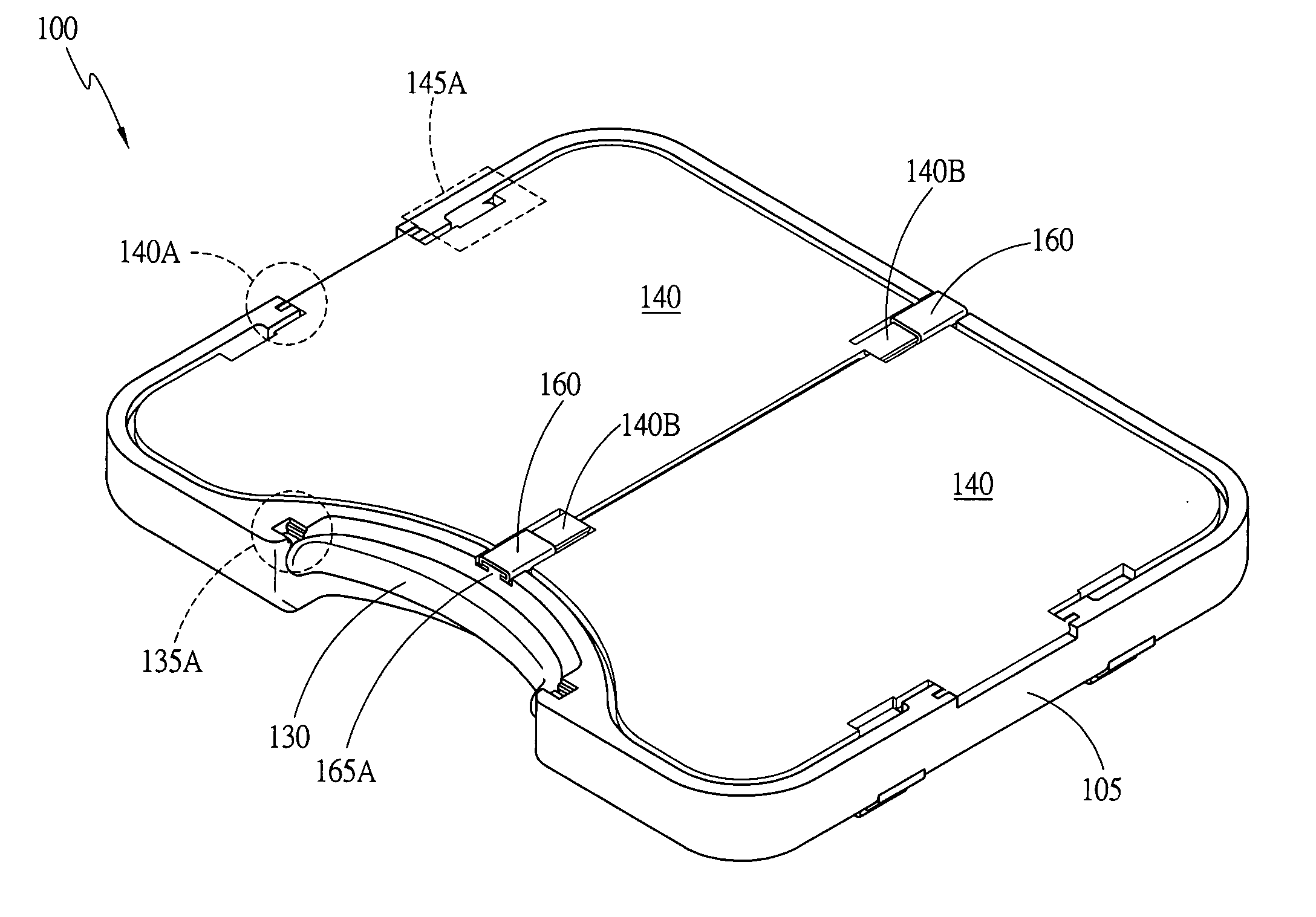
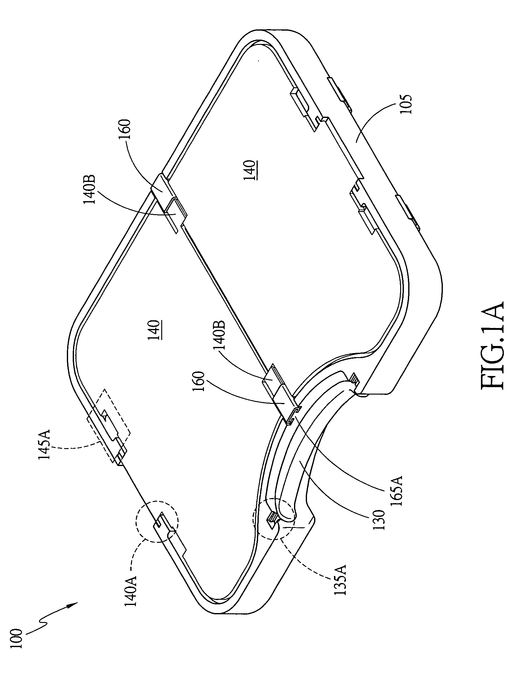
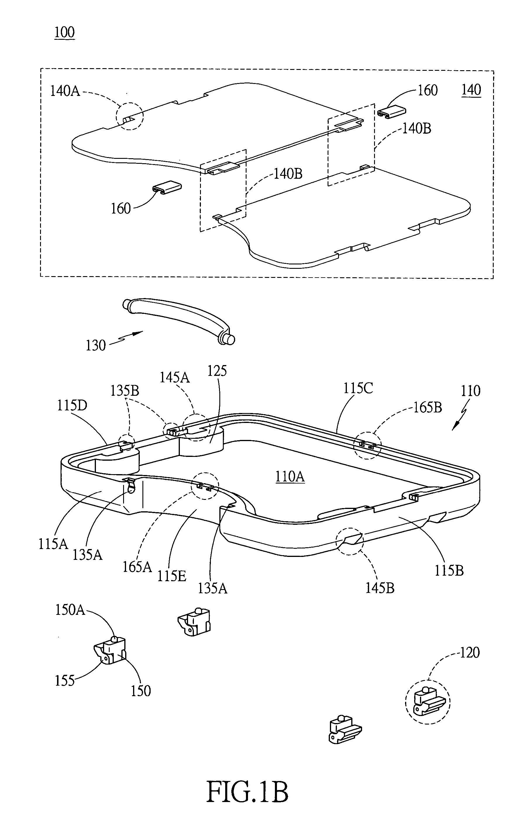
[0014] Referring to FIG. 1A and 1B, in the present invention there is provided a stackable box 100 which comprises a container 110, a plurality of supporting elements 120, a hand-held bar 130, and two transparent lids 140. The container 110 comprises a unified, laddered sidewall 105 surrounding a first surface of a plate 110A to enclose out a basin for containing stuff. As shown, the laddered sidewall 105 comprises an outer wall 115 and an inner wall 125, wherein the outer wall 115 is slightly higher than the inner wall 125 so that when the transparent lids 140 are closed, the transparent lids 140 can be supported by the inner wall 125 and the top surfaces of the transparent lids 140 are as high as the top surface of the outer wall 115. Furthermore, the outer wall 115 comprises (in turn) a first surface 115A, a second surface 115B, a third surface 115C, and a fourth surface 115D, wherein the first surface 115A and the third surface 115C face each other and the second surface 115B an...

second embodiment

[0016] Referring to FIG. 2A to 2C, in the present invention there is provided a stackable box 200 which comprises a container 210, a plurality of supporting elements 220, a hand-held bar 230, and a transparent lid 240. The container 210 comprises a unified, laddered sidewall 205 surrounding a first surface of a plate 210A to enclose out a basin for containing stuff. As shown, the laddered sidewall 205 comprises an outer wall 215 and an inner wall 225, wherein the outer wall 215 is slightly higher than the inner wall 225 so that when the transparent lid 240 is closed, the transparent lid 240 can be supported by the inner wall 225 and the top surface of the transparent lid 240 is as high as the top surface of the outer wall 215. Furthermore, the outer wall 215 comprises (in turn) a first surface 215A, a second surface 215B, a third surface 215C, and a fourth surface 215D, wherein the first surface 215A and the third surface 215C face each other and the second surface 215B and the four...


PUM


Abstract

The present invention provides a stackable box which comprises a container, a plurality of supporting elements, a hand-held bar and two transparent lids. The container has a concave structure on its sidewall for accepting the hand-held bar. In addition, the container has a plurality of mouths on its sidewall to attach to the supporting elements of another provided stackable box so the two or more provided stackable boxes can form a stacked, unit for use; when not in use, the supporting elements can be accepted inside a plurality of mouths on the back of the container.

Description

BACKGROUND OF THE INVENTION [0001] 1. Field of the Invention [0002] The present invention generally relates to a box, and more particularly to a stackable box. [0003] 2. Description of the Prior Art [0004] Today, items are produced constantly day and night to meet various requirements and needs. For storing personal items, tools, and peripherals, various boxes are designed to these purposes, such as pencil case, etui, toolbox, and storage box. Various items could be managed, stored, and categorized by being placed in these boxes. A good storage box design does not only save the manufacturing cost but also save the space the produced box is going to occupy. In contrast, an ill storage box design will not only increase the manufacturing cost and the space the produced box is going to occupy, but also cause inconvenience to their users. A typical box usually comprises a container and a lid. Moreover, a typical box usually has a joint to link the lid and the container in a way that the ...

Claims


Application Information

Patent Timeline
Patent Type & Authority Applications(United States)
IPC IPC(8): B65D51/04
CPCB65D21/0212B65D43/164B65D25/2841B65D21/0219
Inventor SU, CHUNG-SUNG
Owner TOP GOAL ENTERPRISE
Learn More