
Handle for a power tool

a power tool and handle technology, applied in the direction of portable power tools, grinding machines, metal-working apparatuses, etc., can solve the problems of hand injury, rapid fatigue of operators, and inability to ergonomically favor the and achieve the effect of favorable gripping of the handl

Inactive Publication Date: 2006-02-02
HILTI AG
View PDF25 Cites 27 Cited by
  • Summary
  • Abstract
  • Description
  • Claims
  • Application Information

AI Technical Summary

Benefits of technology

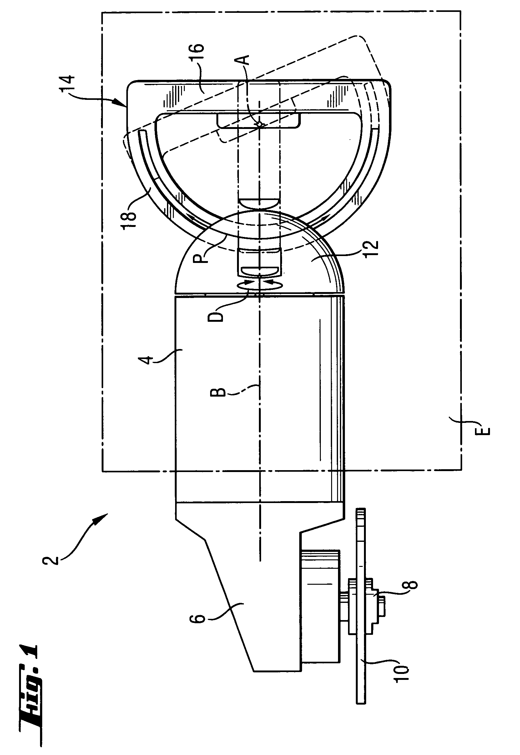
[0009] These and other objects of the present invention, which will become apparent hereinafter, are achieved by providing a hand-held power tool the main handle of which in addition to rotation about a rotational axis, is also can be adjustably inclined to the rotational axis. Thereby, in addition to an adjustable rotational position, the inclination of the main handle relative to the housing can be changed. In this way, numerous possibilities of arrangement of the handle relative to the housing are obtained. Thus, for a particularly large number of possible applications of the hand-held power tool, an ergonomically favorable gripping of the handle becomes possible.

Problems solved by technology

A drawback of the prior art power tool consists in that for some applications, despite presence of the rotatable support of the main handle, no ergonomically favorable gripping of the handle is possible.
This can result in a hand injury and / or in rapid fatigue of the operator.

Method used


Image

  • Handle for a power tool
  • Handle for a power tool
  • Handle for a power tool

Examples


Embodiment Construction

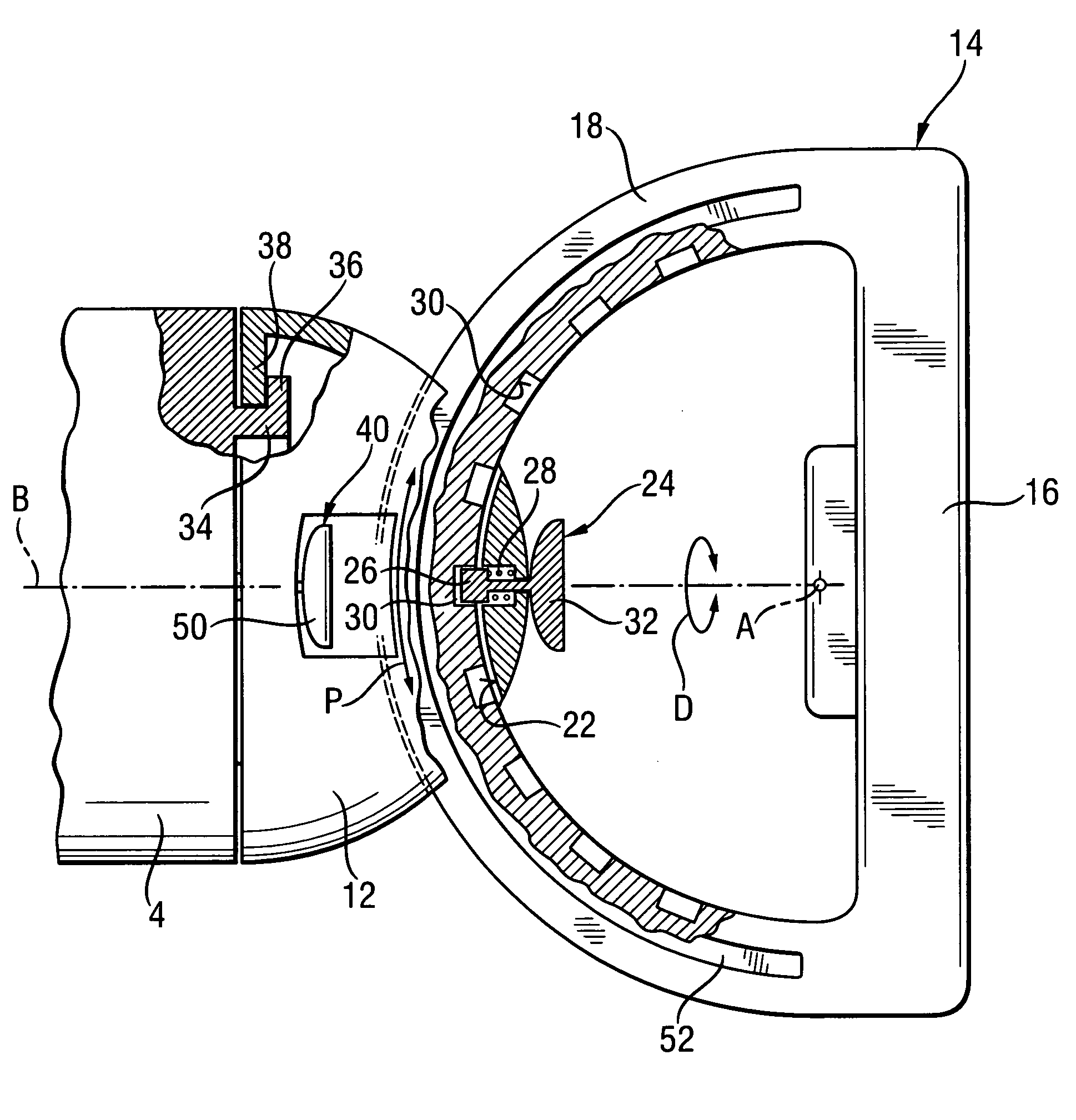
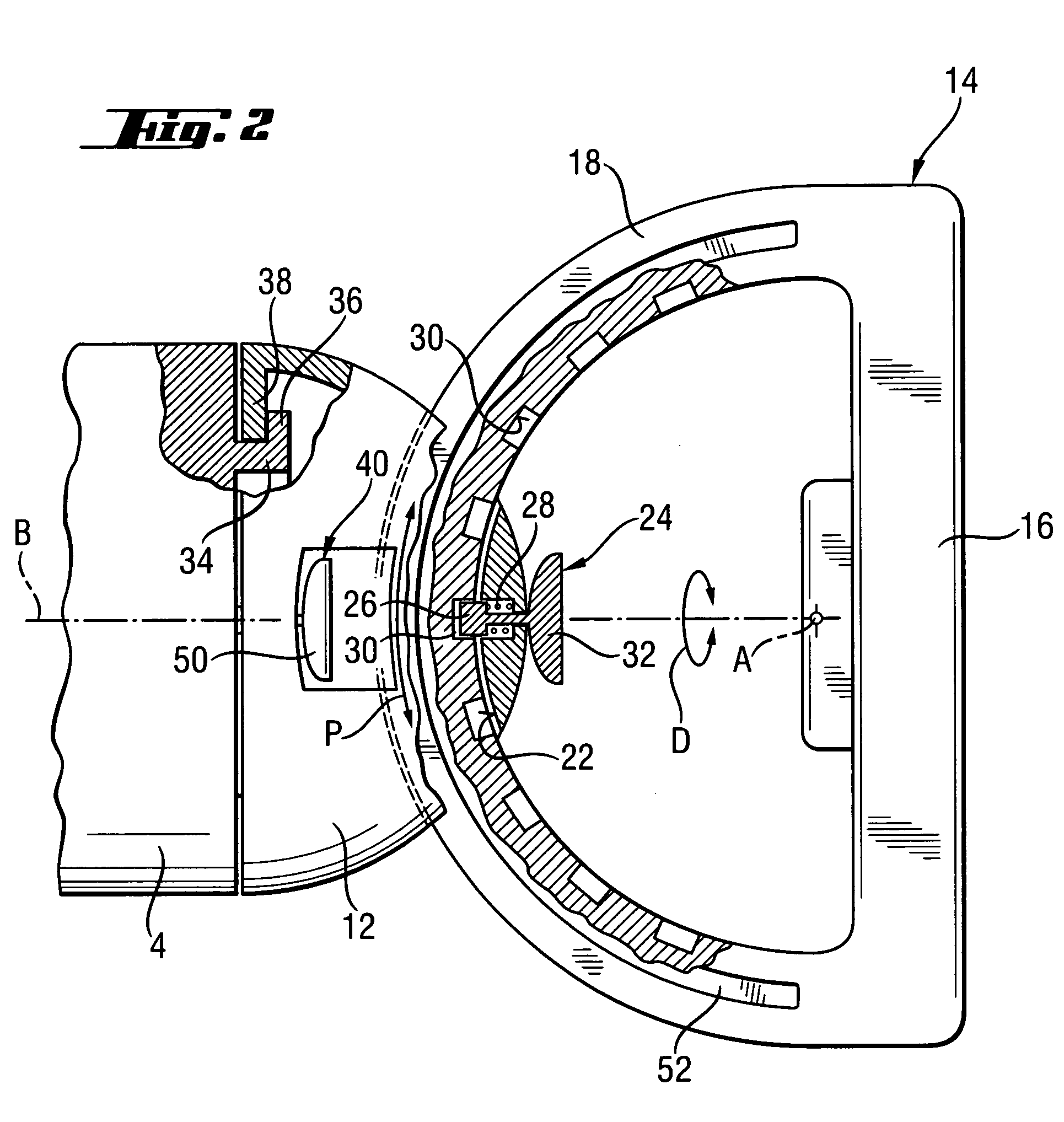
[0023] A hand-held power tool 2, which is shown in FIG. 1 and is formed as an angle grinder, has a housing 4 that forms, at its working tool side end, a tool head 6 with a working tool holder 8 for supporting a working tool 10 in form of a disc is provided.

[0024] At a handle side end of the housing 4 remote from the working tool side end of the housing, there is provided a support member 12 secured on the housing 4 with a possibility of rotation about a rotational axis B in a rotational direction D. The axis B coincides with the main axis of the substantially cylindrical housing 4.

[0025] The support member 12 permanently connects a D-shaped main handle 14 with the housing 4. The main handle 14 can rotate, together with the support member 12, about the axis B to a different rotational position relative to the housing 4, as shown with dash-dot lines.

[0026] The main handle 14 is formed essentially of a grip member 16 and an arch member 18 as a one-piece part. The arch member 18 is h...


PUM


Abstract

A hand-held power tool, in particular an angle grinder, includes a housing (4) having, at its working tool side end, a tool head (6) to which a working tool (10) is secured; a main handle (14) connected to the housing (4) at its handle side end remote from the working tool side end of the housing (4), rotatable about a rotational axis (B), and having an adjustably inclined relative to the rotational axis (B).

Description

BACKGROUND OF THE INVENTION [0001] 1. Field of the Invention [0002] The present invention relates to a motor-driven hand-held tool, in particular an angle grinder, having a housing which is provided, at its working tool side end, with a tool head to which a working tool, in particular, a disc-shaped tool is secured. At its handle side end remote from the working tool side end, the housing is connected with a main handle that rotates relative to the housing about a rotational axis. [0003] 2. Description of the Prior Art [0004] Hand-held power tools of the type described above can be used, due to the adjustable main handle, in different applications, with the main handle being rotated or pivoted relative to the housing. Under the term “main handle,” such a handle is understood which, e.g., contrary to an additional side handle, which is put in, if necessary, is provided on the power tool for a lasting use and is gripped with an operator's hand at each conceivable use of the power tool...

Claims


Application Information

Patent Timeline
Patent Type & Authority Applications(United States)
IPC IPC(8): B24B23/00B24B27/08
CPCB25F5/02
Inventor FUNK, ALEXANDER
Owner HILTI AG
Learn More