
Outboard motor

a technology for outboard motors and motors, applied in the field of outboard motors, can solve the problems of degrading operability and large outboard motor size, and achieve the effect of minimizing the increase in size and cos

Inactive Publication Date: 2006-02-02
HONDA MOTOR CO LTD
View PDF6 Cites 31 Cited by
  • Summary
  • Abstract
  • Description
  • Claims
  • Application Information

AI Technical Summary

Benefits of technology

[0012] A first object of this invention is therefore to overcome this problem by providing a hybrid outboard motor that enables engine starting by electric power while minimizing increase in size and cost.
[0014] A second object of this invention is therefore to respond to this issue by providing a hybrid outboard motor that enables efficient cooling of the internal combustion engine and electric motor, as well as the centrifugal clutch installed between them.
[0016] A third object of this invention is therefore to overcome these disadvantages by providing a hybrid outboard motor that enables regulation of electric motor speed and internal combustion engine speed without degrading operability or increasing outboard motor size.
[0017] Aside from the above, conventional outboard motors produce undesirable gear noise owing to the fact that transmission of drive shaft rotation to the propeller shaft is achieved by using a bevel gear to convert rotation around a vertical axis to rotation around a horizontal axis. It is particularly desirable to improve quietness by lowering gear noise in the case of an electrically powered or hybrid outboard motor capable of cruising under the power of a low-noise electric motor.
[0018] A fourth object of this invention is therefore to offer a solution to this issue by providing an outboard motor improved in quietness by reducing the number of gears in the power transmission system between the drive sources and the propeller.
[0020] A fifth object of this invention is therefore to solve this problem by providing an outboard motor that is easy to mount on a boat.

Problems solved by technology

When the fourth prior art taught by '841 is applied to the hybrid outboard motor such as taught by the first prior art '493, the mechanism for regulating the speed of the internal combustion engine needs to be provided separately of the bar handle, which entails the disadvantages of degraded operability and larger outboard motor size.

Method used


Image

  • Outboard motor
  • Outboard motor
  • Outboard motor

Examples


Embodiment Construction

[0041] A preferred embodiment of an outboard motor according to the present invention will now be explained with reference to the attached drawings.

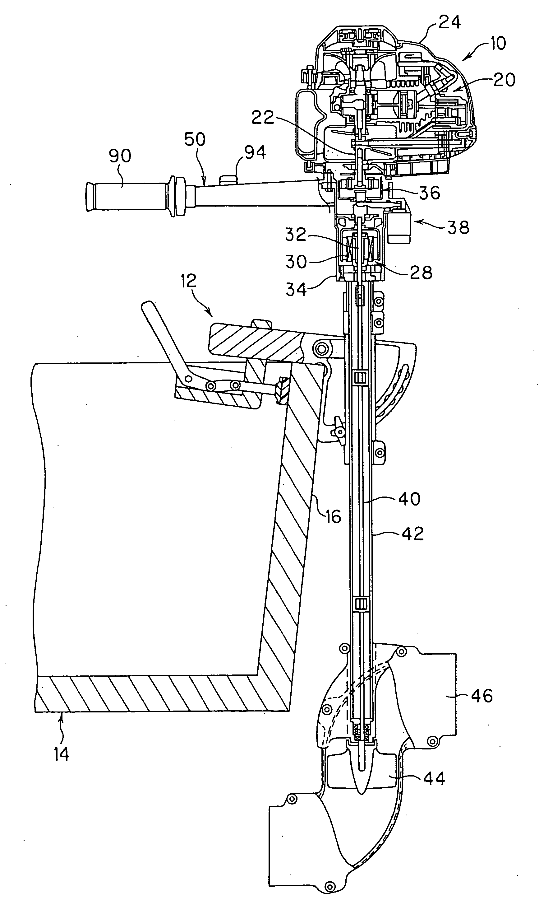
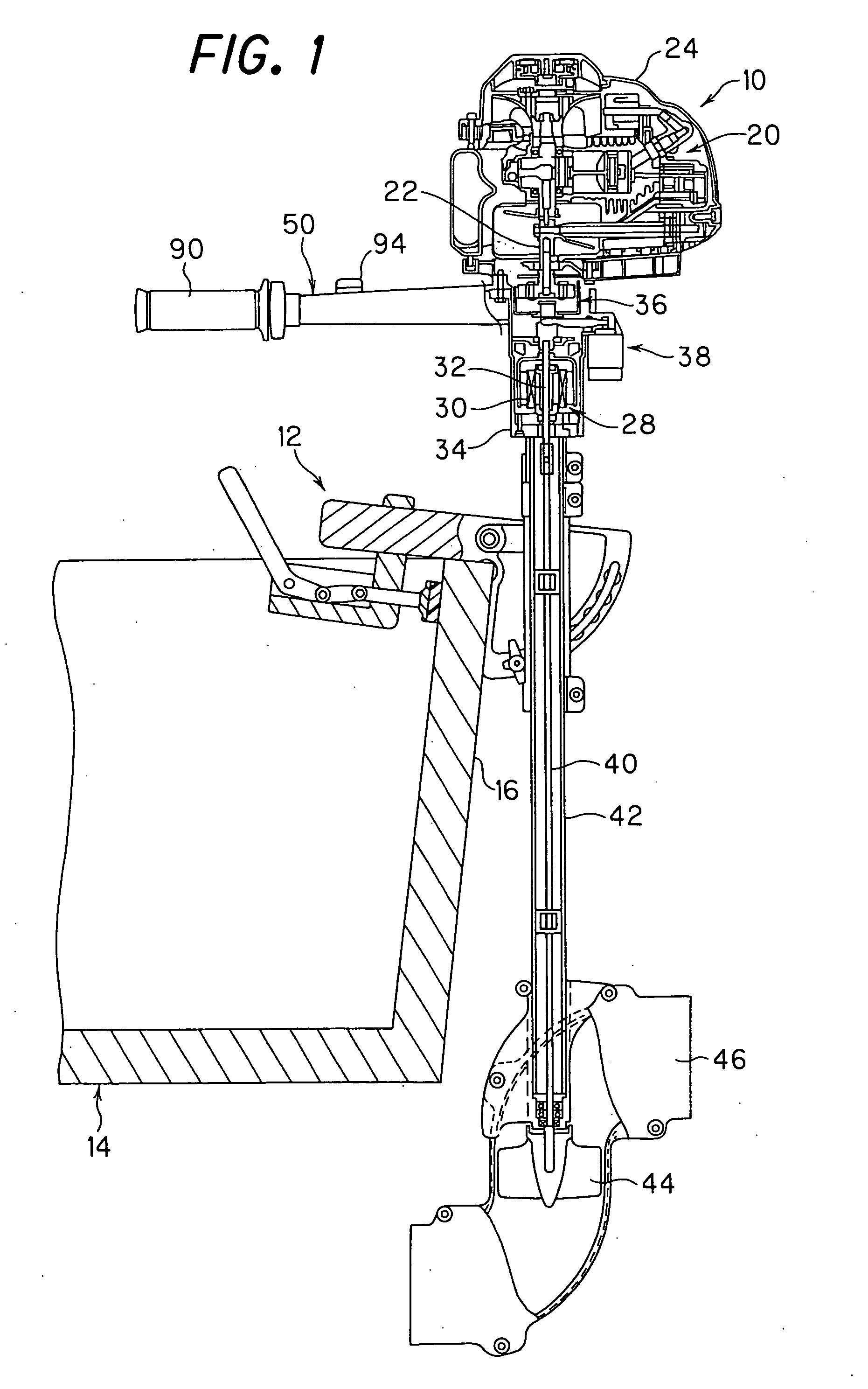
[0042]FIG. 1 is a partially sectional view of an outboard motor according to an embodiment of the invention.

[0043] Symbol 10 in FIG. 1 designates an outboard motor. The outboard motor 10 is mounted on the stern, more specifically on the transom 16 of a boat 14 by means of a mounting device 12.

[0044] The outboard motor 10 is equipped with an internal combustion engine (motor; hereinafter simply referred to as “engine”) 20 at its upper portion. The engine 20 is a one-cylinder gasoline engine with a displacement of about 50 cc capable of producing an output of 1.5 KW (about 2 PS). As shown in the drawing, the engine 20 has its crankshaft (output shaft) 22 aligned vertically and enclosed or covered by an engine cover 24.

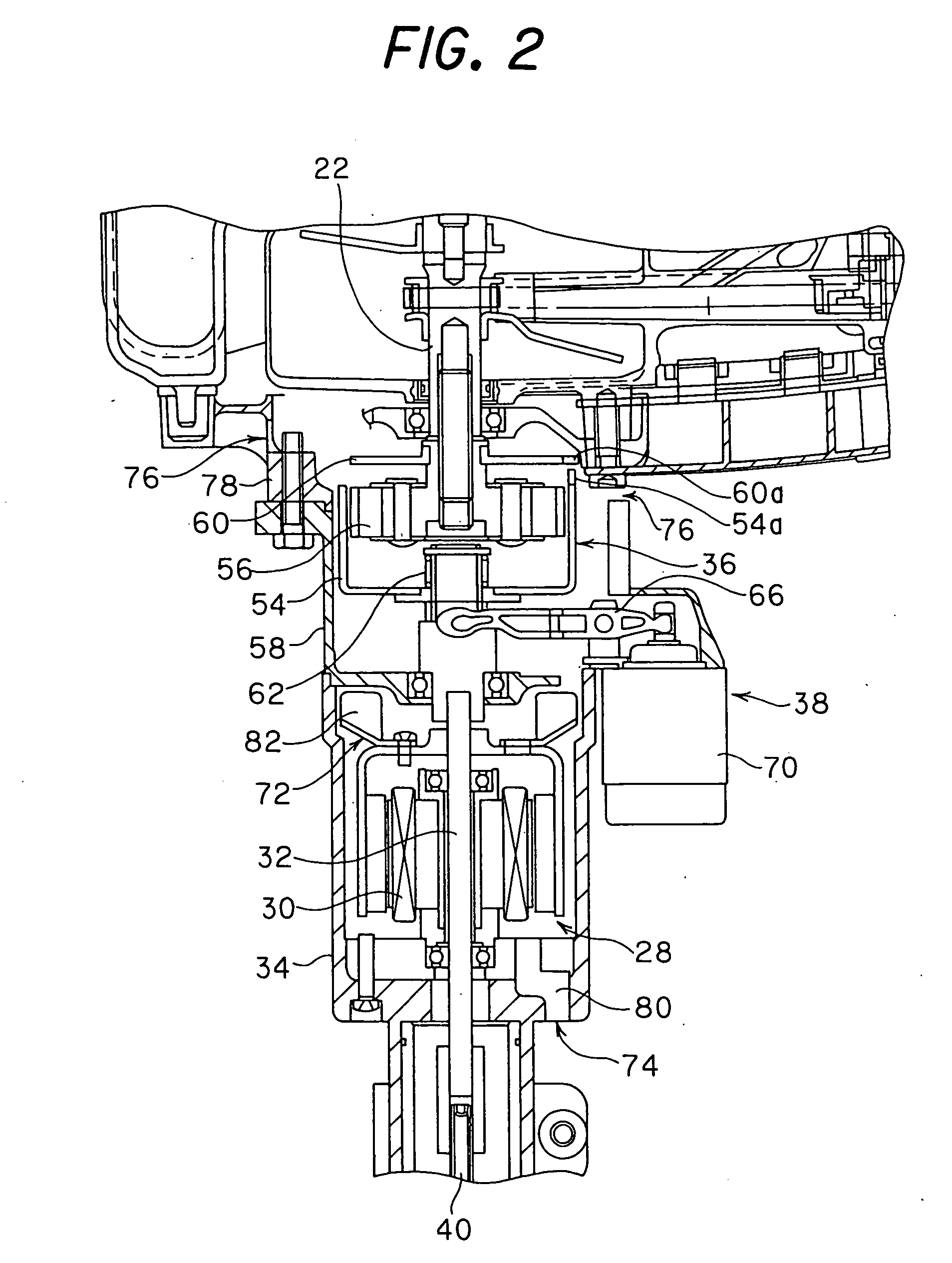
[0045] An electric motor (motor) 28 is installed in the outboard motor 10 vertically downward of the engine 20. The ele...


PUM


Abstract

An outboard motor is equipped with a centrifugal clutch located between the crankshaft of an engine and a rotor of an electric motor for, when the engine operates, transmitting its output to through the rotor to a propeller, and with a motor output transmission mechanism for, when the engine does not operate, transmitting the output of the motor to the crankshaft. The engine can therefore be started by the motor used to drive the propeller. As a result, there is no need to install a separate electric motor for engine starting, so that starting of the engine by electric power can be made possible with minimum increase in the size and cost of the outboard motor.

Description

BACKGROUND OF THE INVENTION [0001] 1. Field of the Invention [0002] This invention relates to an outboard motor mounted on the stern of a boat and having a propeller to propel the boat. [0003] 2. Description of the Related Art [0004] Among of the outboard motors, hybrid outboard motors equipped with an internal combustion engine and an electric motor as propeller drive sources or propulsion unit have been developed. [0005] In the hybrid outboard motors, for selectively transmitting either the output of an internal combustion engine or the output of an electric motor to a propeller, it is conceivable, as taught for example by Japanese Laid-Open Utility Model Application No. Sho 63(1988)-158,493 (e.g., FIG. 5), to connect one end of the output shaft of the electric motor to the output shaft of the internal combustion engine through a centrifugal clutch and connect the other end of the output shaft of the electric motor to the propeller. By this arrangement, during operation of the int...

Claims


Application Information

Patent Timeline
Patent Type & Authority Applications(United States)
IPC IPC(8): B60L11/02B60L50/10
CPCB63H11/107B63H20/02B63H21/20Y02T70/5236B63H2021/205F02N11/00B63H23/30
Inventor KITANI, HIROYUKIMIYASHITA, KAZUMITERADA, SHIGEOHIROSE, TADAFUMI
Owner HONDA MOTOR CO LTD
Learn More