Nip press sensing system including a sensor strip having sensor interface electronics associated therewith and methods of operating the same

a sensor and sensor technology, applied in the field of nip press technology, can solve the problems of fiber crushing as well as holes in the resulting paper product, uneven surface characteristics, poor quality paper, etc., and achieve the effect of facilitating individual addressing

Active Publication Date: 2006-01-26
STOWE WOODWARD
View PDF37 Cites 19 Cited by
  • Summary
  • Abstract
  • Description
  • Claims
  • Application Information

AI Technical Summary

Benefits of technology

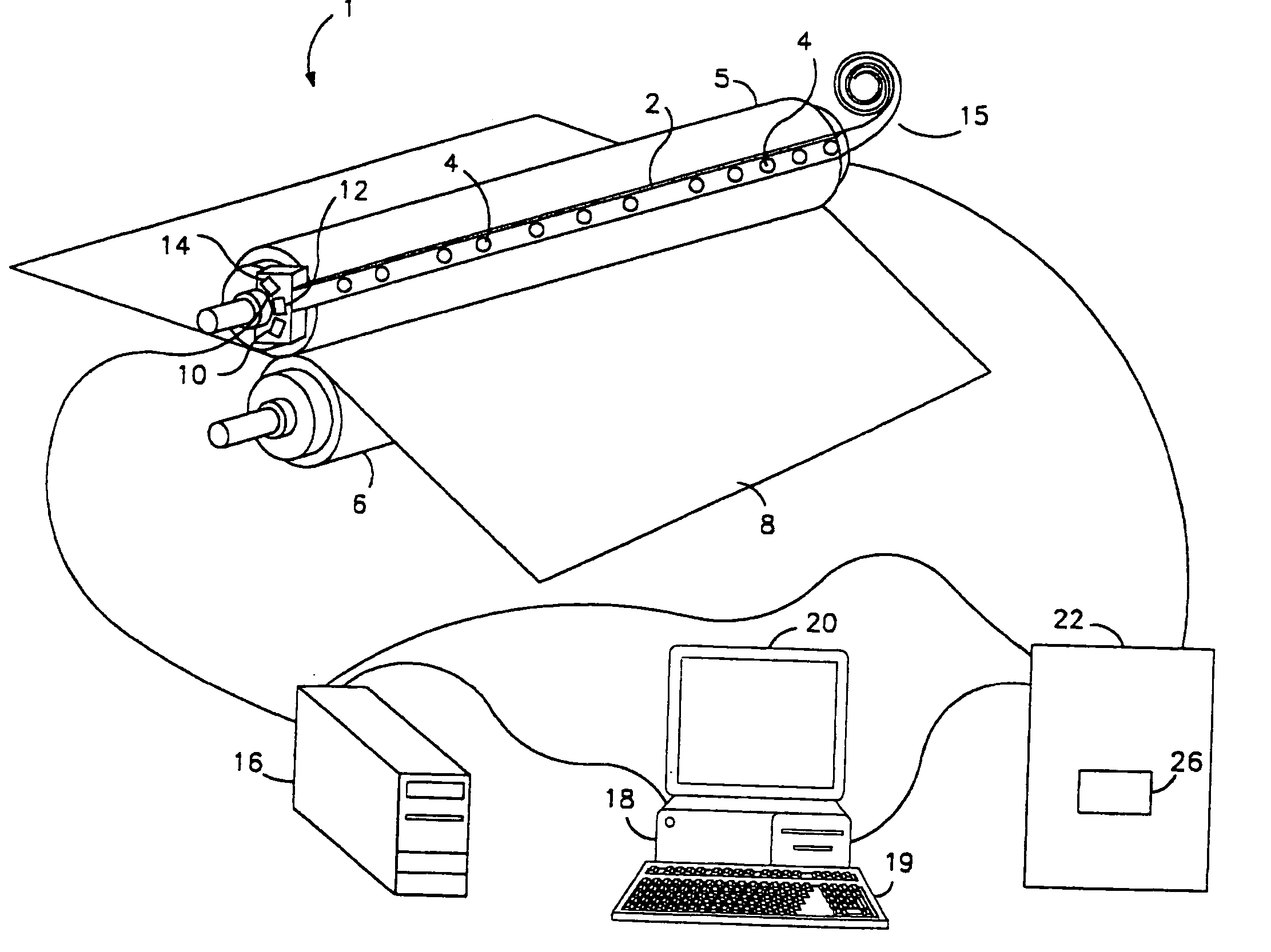
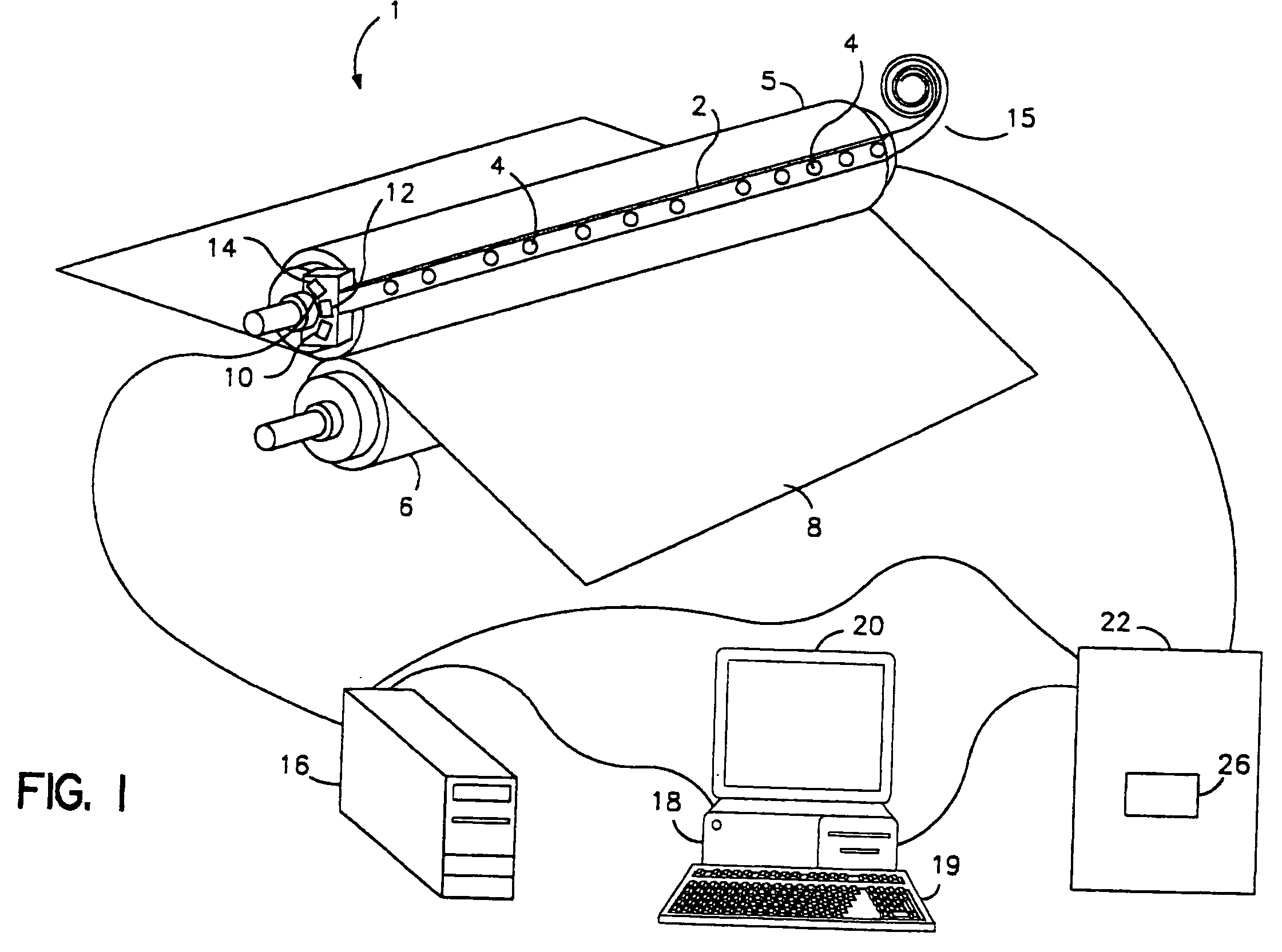
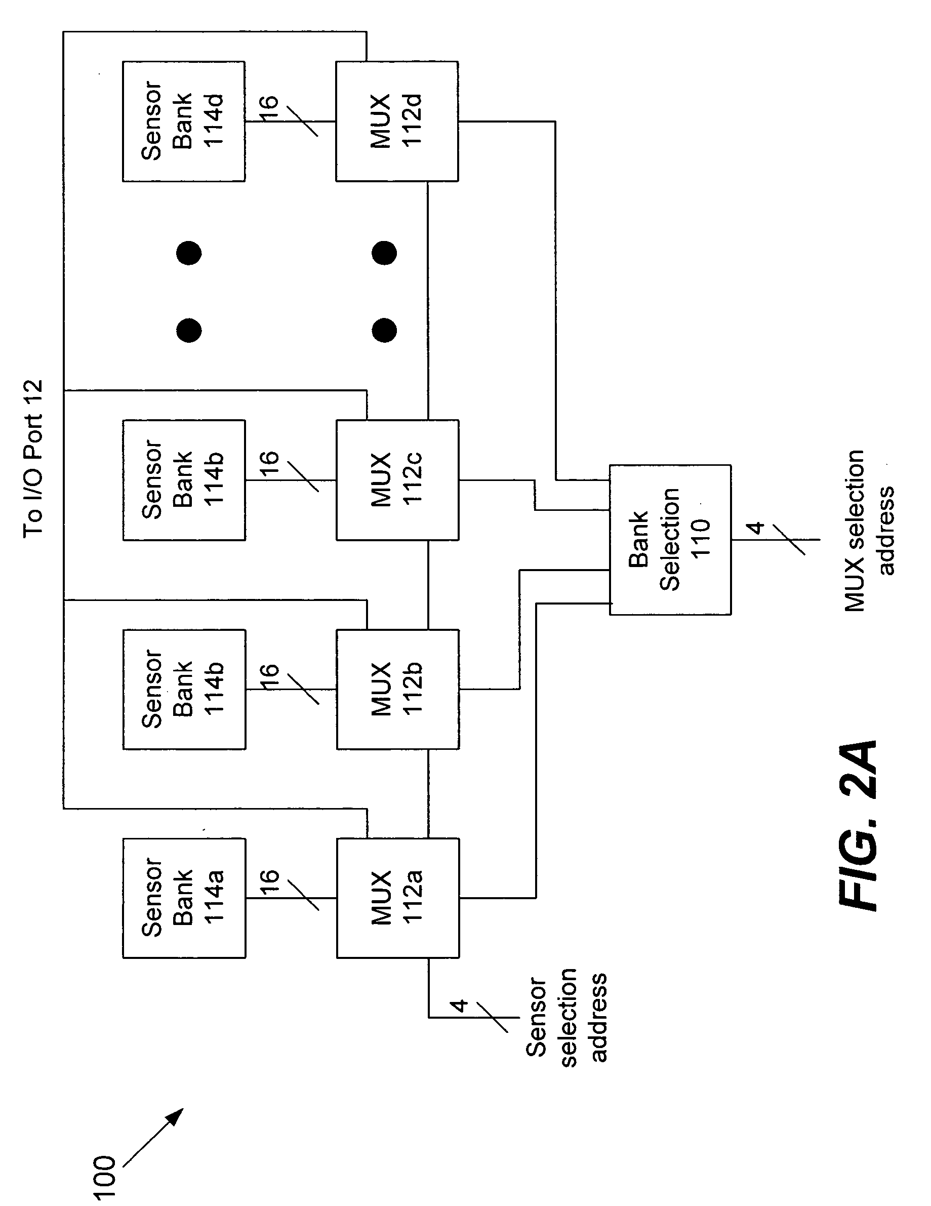
[0009] According to some embodiments of the present invention, a system for determining characteristics of two rolls configured in a nip press includes a strip configured to be placed in the nip press. A plurality of sensors embedded in the strip is configured to generate signals representative of the pressure and / or the nip width between the two rolls. Interface circuitry facilitates addressing of individual ones of the plurality of sensors via a data processing system.

Problems solved by technology

Excessive pressure can cause crushing of fibers as well as holes in the resulting paper product.
Conventional methods addressing this problem have been inadequate, and thus, this problem persists in the nip press stage, often resulting in paper of poor quality, having uneven surface characteristics.
Roll deflection, commonly due to sag or nip loading, is a source of uneven pressure distribution.
Notwithstanding the problem of roll deflection, the problem of uneven loading across the roll length, and in the cross machine direction, persists because pressure is often unevenly applied along the roll.
Unfortunately, conventional technology uses spaced sensors configured in such a way that they may not be able to detect certain nip width variations that occur over small spatial dimensions, such as those near the end of a nipped roll or those near regions having high temperatures.
There is no sheet to insulate the calendar cover from the heated mating roll and the dub has not started to keep the roll materials separated.

Method used


Image

  • Nip press sensing system including a sensor strip having sensor interface electronics associated therewith and methods of operating the same
  • Nip press sensing system including a sensor strip having sensor interface electronics associated therewith and methods of operating the same
  • Nip press sensing system including a sensor strip having sensor interface electronics associated therewith and methods of operating the same

Examples


Embodiment Construction

[0029] While the invention is susceptible to various modifications and alternative forms, specific embodiments thereof are shown by way of example in the drawings and will herein be described in detail. It should be understood, however, that there is no intent to limit the invention to the particular forms disclosed, but on the contrary, the invention is to cover all modifications, equivalents, and alternatives falling within the spirit and scope of the invention as defined by the claims. Like reference numbers signify like elements throughout the description of the figures.

[0030] As used herein, the singular forms “a,”“an,” and “the” are intended to include the plural forms as well, unless expressly stated otherwise. It should be further understood that the terms “comprises” and / or “comprising” when used in this specification is taken to specify the presence of stated features, integers, steps, operations, elements, and / or components, but does not preclude the presence or addition...


PUM

PropertyMeasurementUnit
lengthaaaaaaaaaa
pressureaaaaaaaaaa
interfaceaaaaaaaaaa

Abstract

According to some embodiments of the present invention, a system for determining characteristics of two rolls configured in a nip press includes a strip configured to be placed in the nip press. A plurality of sensors embedded in the strip is configured to generate signals representative of the pressure and/or the nip width between the two rolls. Interface circuitry facilitates addressing of individual ones of the plurality of sensors via a data processing system.

Description

RELATED APPLICATION [0001] This application claims the benefit of and priority to U.S. Provisional Application No. 60 / 571,174, filed May 14, 2004, and entitled Nip Width Measurement System, the disclosure of which is hereby incorporated herein by reference.BACKGROUND OF THE INVENTION [0002] The present invention relates generally to the field of nip press technology and, more particularly, to systems and methods for measuring nip width between loaded rolls in a nip press. [0003] In the process of papermaking, many stages may be required to transform headbox stock into paper. The initial stage is the deposition of the headbox stock onto paper machine clothing or felt. Upon deposition, the white water forming a part of the stock flows through the interstices of the felt, leaving a mixture of water and fiber thereon. The felt then supports the mixture, leading it through several dewatering stages such that only a fibrous web or matt is left thereon. [0004] One of the stages of dewateri...

Claims


Application Information

Patent Timeline
Patent Type & Authority Applications(United States)
IPC IPC(8): G01B11/02D21F3/06G01L5/00
CPCB41F13/24G01L5/0085D21F3/06
Inventor MOORE, ROBERT HUNTERMURPHY, DAVID
Owner STOWE WOODWARD
Why Eureka
Try Eureka