
Light emitting diode and backlight module having light emitting diode

a technology backlight modules, which is applied in the direction of point-like light sources, lighting and heating apparatuses, instruments, etc., can solve the problems of loss of brightness of light emitting diodes, poor color rendition of liquid crystal display devices, etc., to improve the color saturation of liquid crystal display televisions, increase color saturation, and increase color saturation

Inactive Publication Date: 2006-01-19
CHI LIN TECH CO LTD
View PDF9 Cites 170 Cited by
  • Summary
  • Abstract
  • Description
  • Claims
  • Application Information

AI Technical Summary

Benefits of technology

[0009] One objective of the present invention is to improve the color saturation of a liquid crystal display television (LCD TV) or a liquid crystal display device.
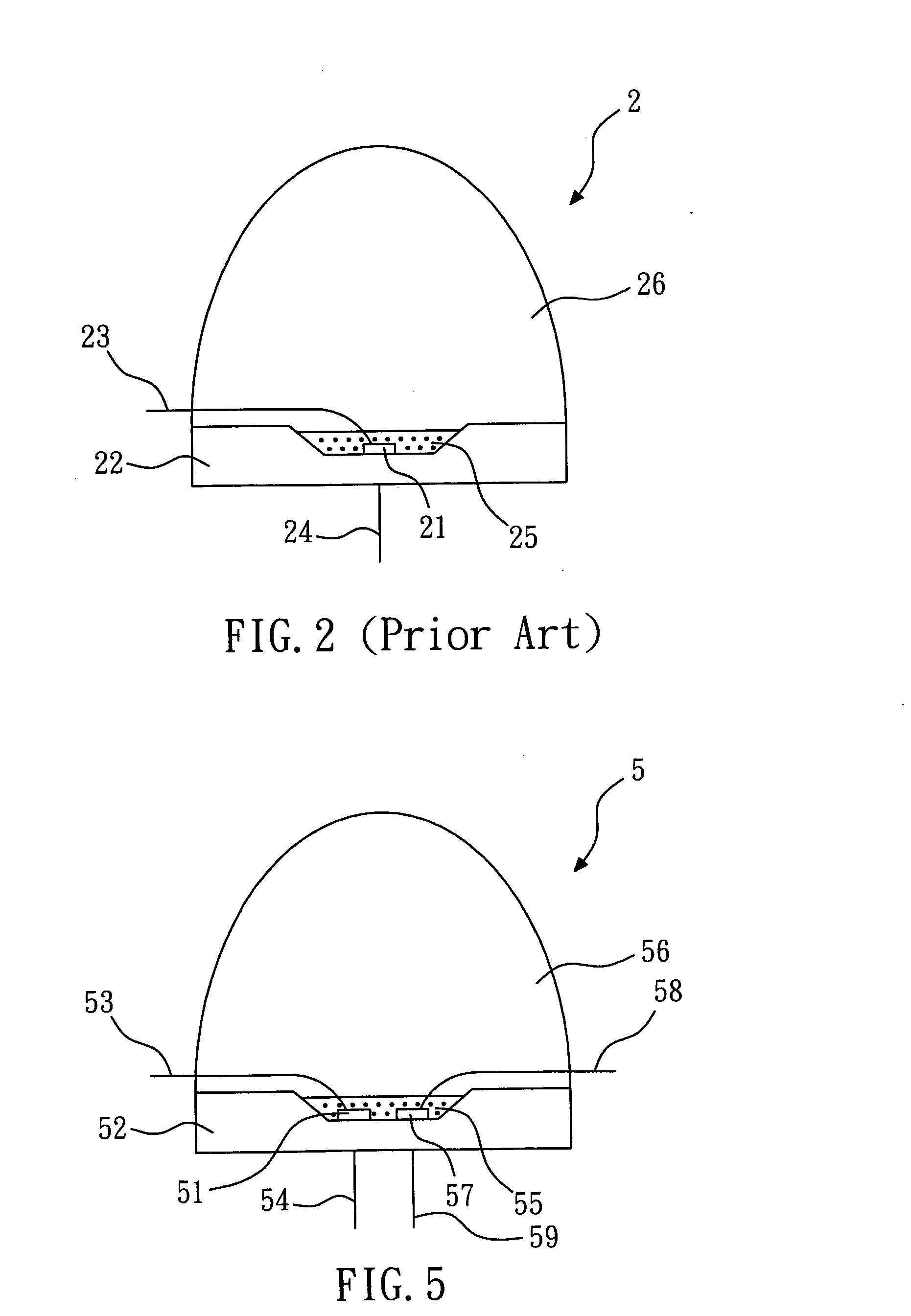
[0010] Another objective of the present invention is to provide a light emitting diode that has a blue die and a red die so as to compensate the red deficiency in the output light. When the light emitting diode is used as a light source of a backlight module, it can increase the color saturation.
[0011] Another objective of the present invention is to provide a backlight module that has cold cathode fluorescent lamps and green light emitting diodes so as to compensate the green deficiency in the output light. When the backlight module is used as a light source of a liquid crystal display television or a liquid crystal display device, it can increase the color saturation.
[0012] Another objective of the present invention is to provide a backlight module that has white light emitting diodes and red light emitting diodes so as to compensate the red deficiency in the output light. When the backlight module is used as a light source of a liquid crystal display television or a liquid crystal display device, it can increase the color saturation.

Problems solved by technology

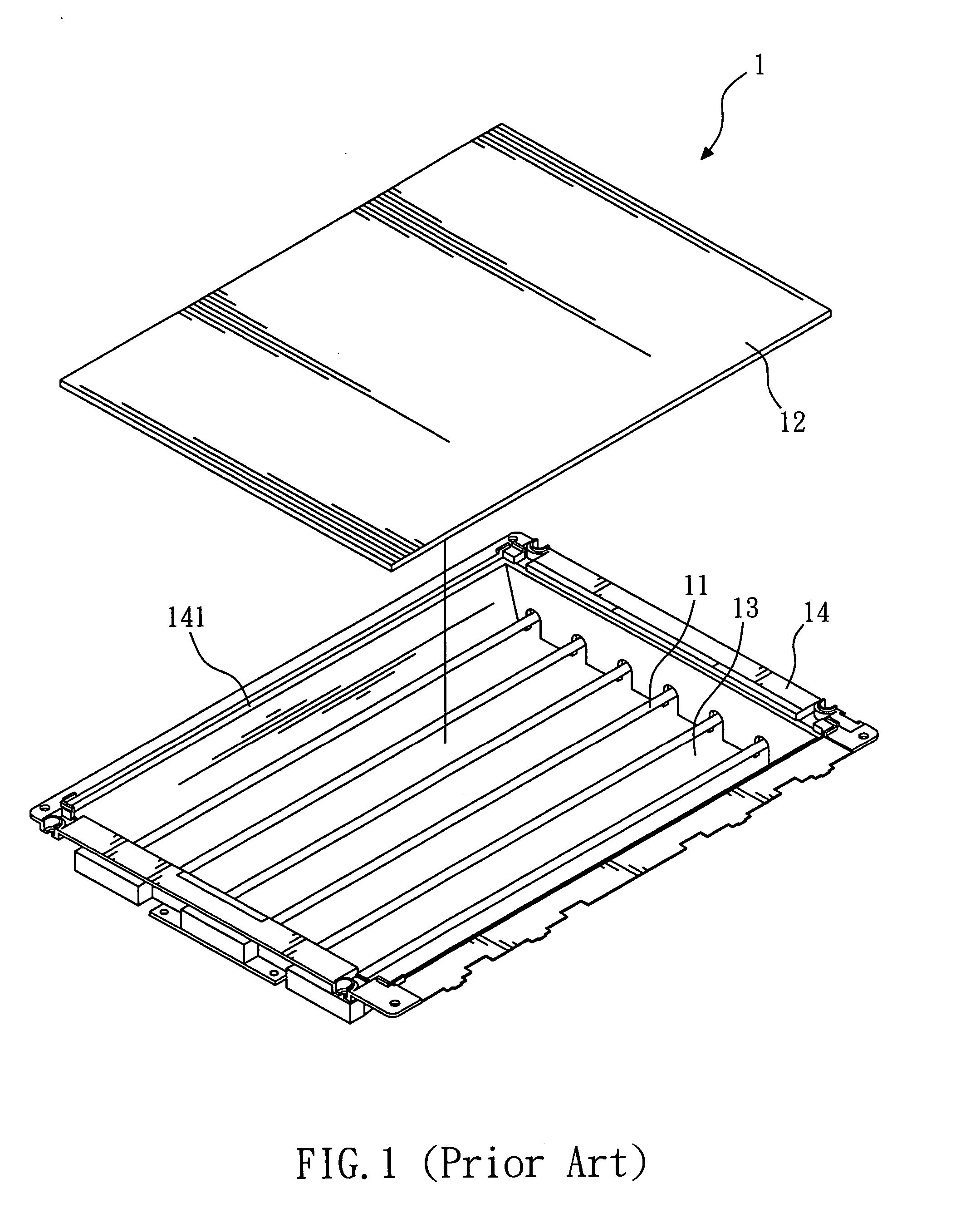
When the conventional backlight module 1 is applied in a liquid crystal display device, the green color is weakly displayed on the liquid crystal display device, which causes poor color rendition.
When being used as a light source of a backlight for a liquid crystal display device, the red deficiency in the output light causes poor color rendition of the liquid crystal display device.
However, such way will cause loss in brightness of the light emitting diode.
Therefore, when being used as a light source of backlight module, it will reduce the brightness of the display device.

Method used


Image

  • Light emitting diode and backlight module having light emitting diode
  • Light emitting diode and backlight module having light emitting diode
  • Light emitting diode and backlight module having light emitting diode

Examples


Embodiment Construction

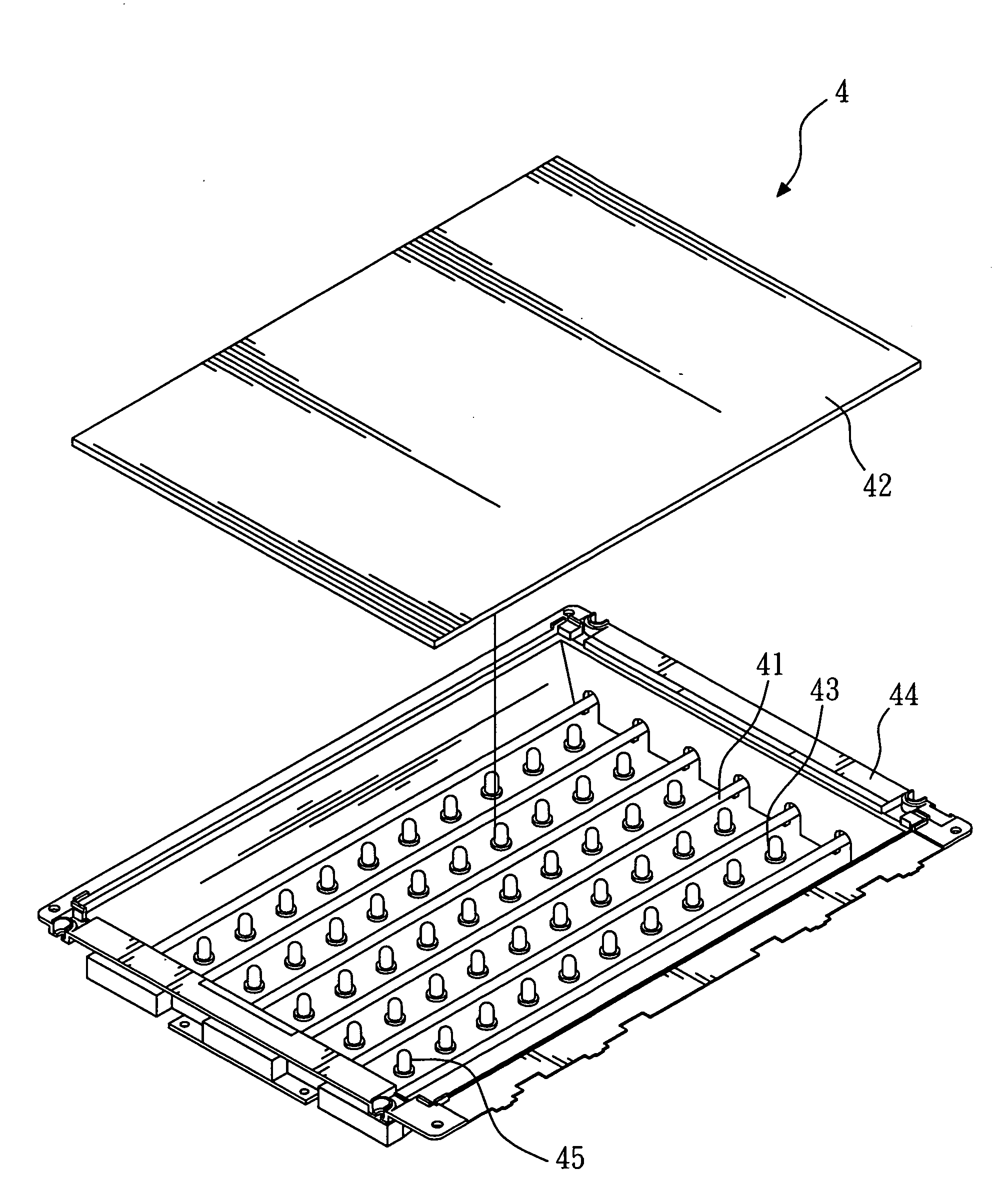
[0021]FIG. 4 shows a perspective view of a backlight module according to the present invention, wherein the light emitting diodes adapted in the backlight module are conventional. The backlight module 4 comprises a plurality of lamps 41, a diffusion plate 42, a reflective plate 43, a housing 44 and a plurality of green light emitting diodes 45.

[0022] The backlight module 4 is disposed under a liquid crystal plate in a liquid crystal display device (not shown in the figure). The lamps 41 are cold cathode fluorescent lamps and are used for providing light beams. The reflective plate 43 is disposed under the lamps 41 and is used for reflecting light beams generated by the lamps 41 to the diffusion plate 42. The diffusion plate 42 is disposed above the lamps 41 and is used for diffusing the light beams generated by the lamps 41 and the green light emitting diodes 45 and reflected by the reflective plate 43 so that the liquid crystal plate has an even distribution of light beams. The ho...


PUM


Abstract

The present invention relates to a light emitting diode comprising a blue die and a fluorescent material layer. The blue die is used for generating blue light when being activated. The fluorescent material layer is used for generating yellow light when being activated. The light emitting diode further comprises a red die that is used for generating red light when being activated, so as to increase the red color component of the output light of the light emitting diode. The present invention also relates to a backlight module having light emitting diode, which has a well-balanced color when being used for a light source of a liquid crystal display or a liquid crystal display television.

Description

BACKGROUND OF THE INVENTION [0001] 1. Field of the invention [0002] The present invention relates to a light emitting diode and backlight module having light emitting diode, particularly to a light emitting diode and backlight module that has an output light of well-balanced color. [0003] 2. Description of the Related Art [0004]FIG. 1 shows a perspective view of a conventional backlight module. The conventional backlight module 1 comprises a plurality of lamps 11, a diffusion plate 12, a reflective plate 13 and a housing 14. The backlight module 1 is disposed under a liquid crystal plate in a liquid crystal display device (not shown in the figure). The lamps 11 are used for providing light beams. The reflective plate 13 is disposed under the lamps 11 and is used for reflecting light beams generated by the lamps 11 to the diffusion plate 12. The diffusion plate 12 is disposed above the lamps 11 and is used for diffusing the light beams generated by the lamps 11 and reflected by the r...

Claims


Application Information

Patent Timeline
IPC IPC(8): F21V11/00H01L33/32H01L33/50H01L33/56H01L33/60H01L33/62
CPCG02F1/133603G02F1/133604G02F2001/133614H01L25/0753H01L33/44H01L2924/0002H01L33/50H01L2924/00G02F1/133614G01B21/04
Inventor LEE, I-CHANG
Owner CHI LIN TECH CO LTD
Learn More