
Apparatus and method for separating magnetic particles

a technology of magnetic particles and apparatus, applied in the direction of filtration separation, separation process, instruments, etc., can solve the problems of fluid proposal, method of efficiently separating a predetermined amount of particles, etc., and achieve the effect of significantly reducing the amount of foreign substances carried over

Inactive Publication Date: 2006-01-19
CANON KK
View PDF2 Cites 40 Cited by
  • Summary
  • Abstract
  • Description
  • Claims
  • Application Information

AI Technical Summary

Benefits of technology

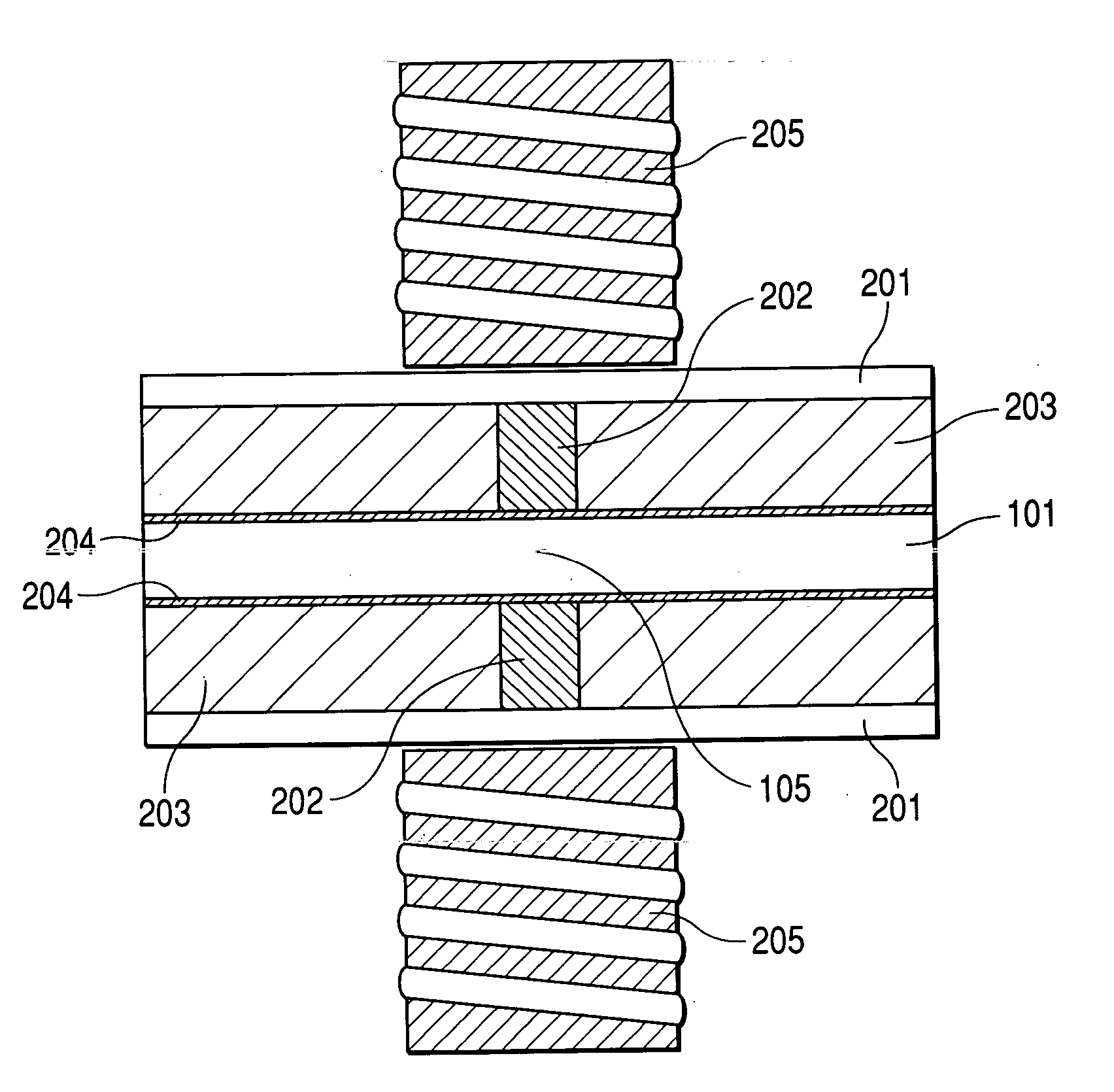
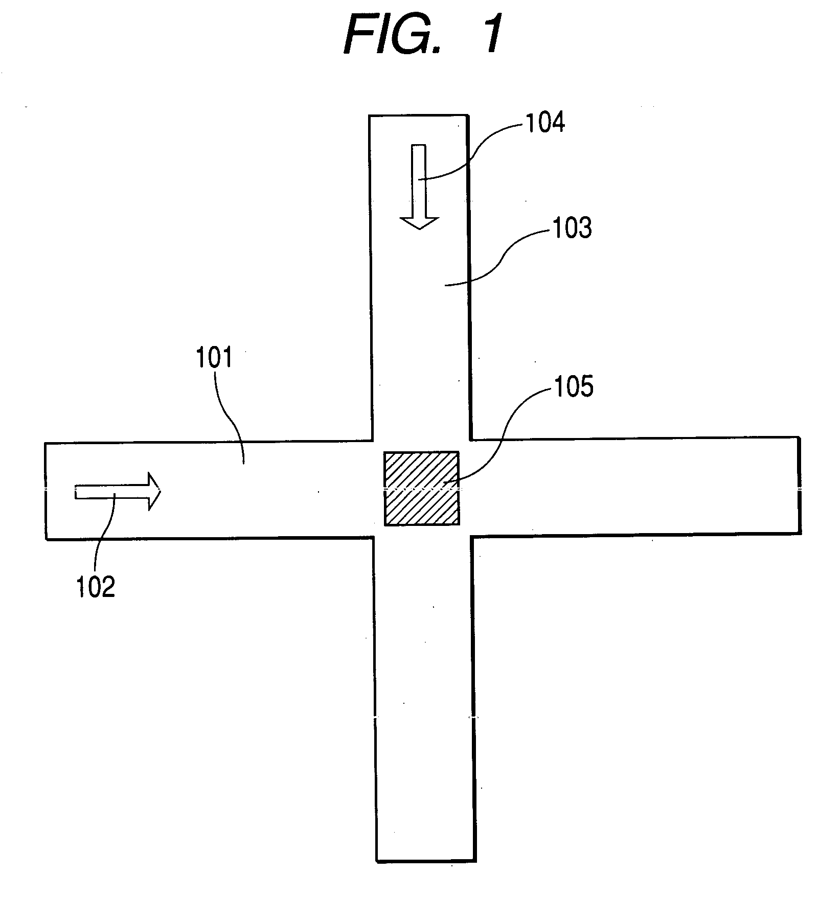
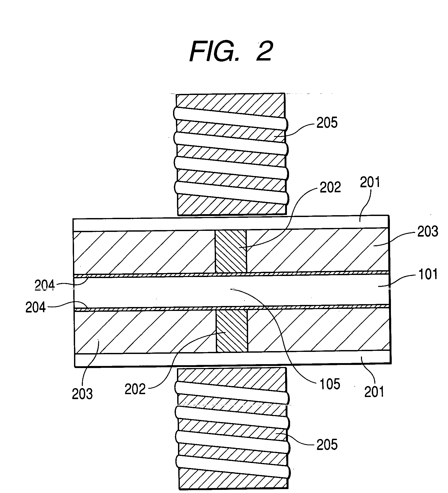
[0016] A first effect of the present invention is that because magnetic particles supplied from the first low channel to the intersection of the flow channels are captured and then discharged to the second flow channel, the amount of a medium carried over from the first flow channel to the second flow channel can be limited to an amount corresponding to the volume of the intersection of the flow channels. In addition, because magnetic particles are discharged to the second flow channel after they are captured in the intersection, the ratio of the medium carried over from the first flow channel to the desired magnetic particles to be captured can be reduced with respect to the amount of the particles. That is, the amount of foreign substances carried over can be considerably reduced with respect to the amount of the desired particles to be captured.
[0017] A second effect of the present invention is that because the amount of magnetic particles to be captured in the intersection can be controlled according to variations in the amount of a fluid sent to the first flow channel, any amount of magnetic particles can be discharged to the second flow channel. When this advantage is combined with, for example, a sensor for measuring the amount of an unknown substance in a fluid, particles having any concentration can be supplied to the sensor portion so that the concentration falls within the detection range of the sensor.

Problems solved by technology

Besides, a method of efficiently separating a predetermined amount of particles from particles dispersed in a fluid has not been proposed yet.

Method used


Image

  • Apparatus and method for separating magnetic particles
  • Apparatus and method for separating magnetic particles
  • Apparatus and method for separating magnetic particles

Examples


example 1

[0053] At first, as a first example, an apparatus in which a target substance in a sample is captured by magnetic particles and the magnetic particles together with the captured target substance are collected will be described with reference to FIG. 5.

[0054] At first, an apparatus for capturing and separating a target substance shown in FIG. 5 was used as a fluid conveyance portion. In FIG. 5, reference numeral 501 denotes a port (pump connection portion) for supplying a sample containing a target substance. Reference numeral 502 denotes a port for supplying a capture reagent containing magnetic particles. Reference numeral 503 denotes a reaction flow channel for reacting a sample with a capture reagent. Reference numeral 504 denotes weak magnetic field application means for promoting a reaction between a capture reagent and a sample in the reaction flow channel. The first flow channel 101 is used as a flow channel for conveying the mixed solution of a sample and a capture reagent ...


PUM

PropertyMeasurementUnit
Particle sizeaaaaaaaaaa
Magnetic fieldaaaaaaaaaa
Sensitivityaaaaaaaaaa

Abstract

An apparatus for separating a predetermined amount of magnetic particles in a fluid, including a fluid conveyance portion having at least a first flow channel for supplying a fluid containing the magnetic particles, a second flow channel for discharging the separated magnetic particles, and an intersection at which the first flow channel and the second flow channel intersect each other, a capture unit for capturing a predetermined amount of the magnetic particles in the fluid supplied from the first flow channel to the intersection when a magnetic field is applied to the intersection of the fluid conveyance portion, and a discharge unit for removing the magnetic field applied to the intersection to discharge the magnetic particles captured by the capture unit by way of a medium introduced into the second flow channel.

Description

BACKGROUND OF THE INVENTION [0001] 1. Field of the Invention [0002] The present invention relates to an apparatus for separating magnetic particles and a separation method using the apparatus as well as an apparatus for capturing and separating particular substances in a fluid using magnetic particles. Of those substances, the present invention particularly relates to the capture and separation of biomolecules such as proteins, sugars, lipids, and nucleic acids, cells, or the like contained in samples derived from organisms. The present invention further relates to a detection apparatus for quantifying the amount of particular substances using the capture and separation function described above. [0003] 2. Related Background Art [0004] Approaches for separating particular substances in samples by the use of particles are known and are large in number. In separation approaches using magnetic particles, which are intended by the present invention, surface-modified magnetic particles as...

Claims


Application Information

Patent Timeline
IPC IPC(8): C02F1/48
CPCC02F1/488
Inventor UTSUNOMIYA, NORIHIKO
Owner CANON KK
Learn More