
Can dispensing package

a can and packaging technology, applied in the direction of instruments, transportation and packaging, apparatus for dispensing discrete objects, etc., can solve the problems of structural integrity compromise of the carton, and achieve the effects of easy opening, resistance to further tearing, and easy opening

Inactive Publication Date: 2006-01-05
GRAPHIC PACKAGING INT
View PDF30 Cites 20 Cited by
  • Summary
  • Abstract
  • Description
  • Claims
  • Application Information

AI Technical Summary

Benefits of technology

This patent describes a new type of dispenser for cans made up of multiple layers inside a carton. The goal was to create a device that could be easily opened without fully removing its contents, while also providing access to see what's inside the container. Additionally, it should resist excessive tearing and make it easier to start with just by design.

Problems solved by technology

The technical problem addressed in these two patents is how to create a full-enclosed carton that allows easy access to its contents without sacrificing the strength of the overall structure of the carton.

Method used


Image

  • Can dispensing package
  • Can dispensing package
  • Can dispensing package

Examples


Embodiment Construction

[0026] The present invention is intended primarily for use with cans, and other types of cylindrical containers, used to contain soft drinks, beer and the like.

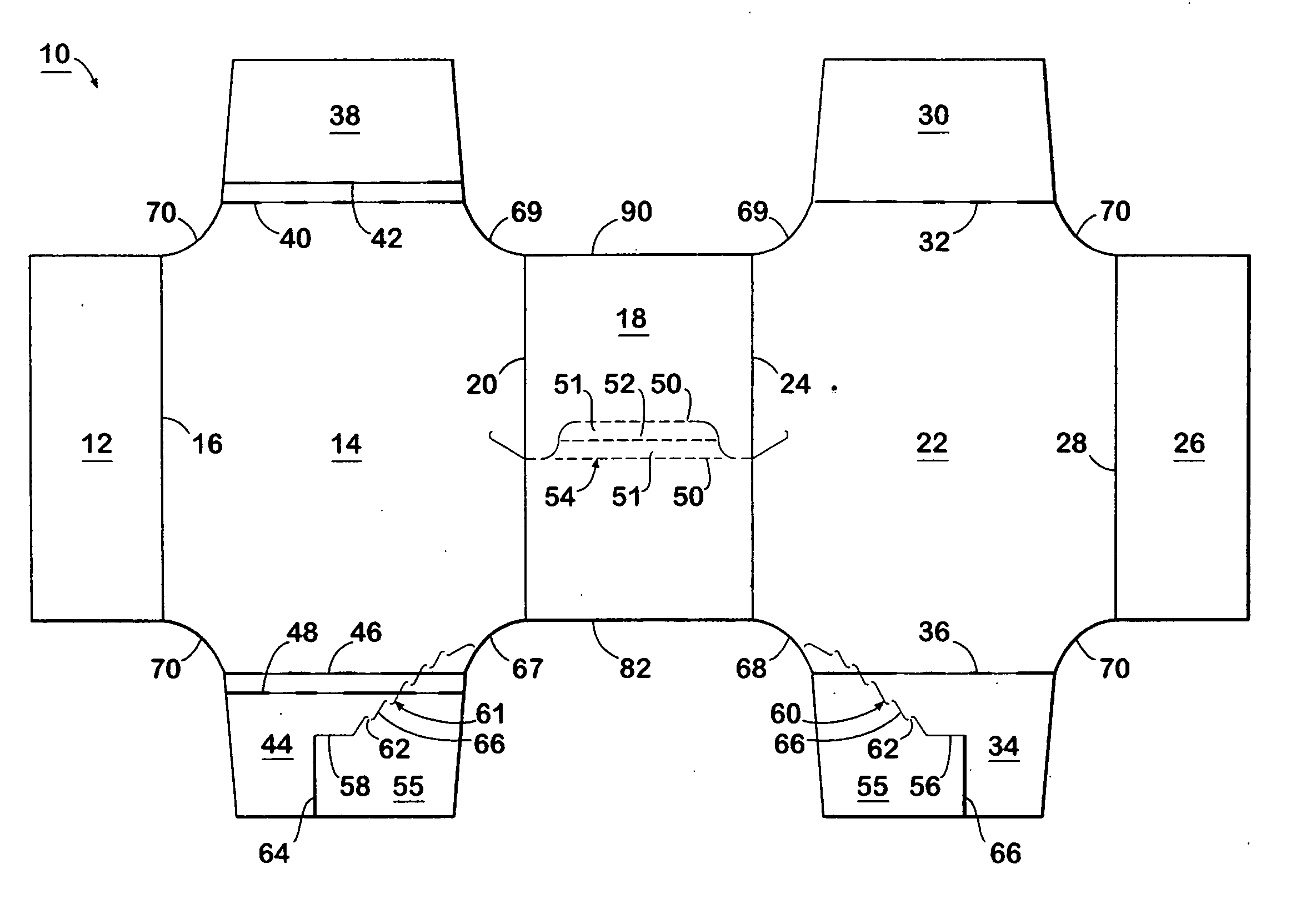
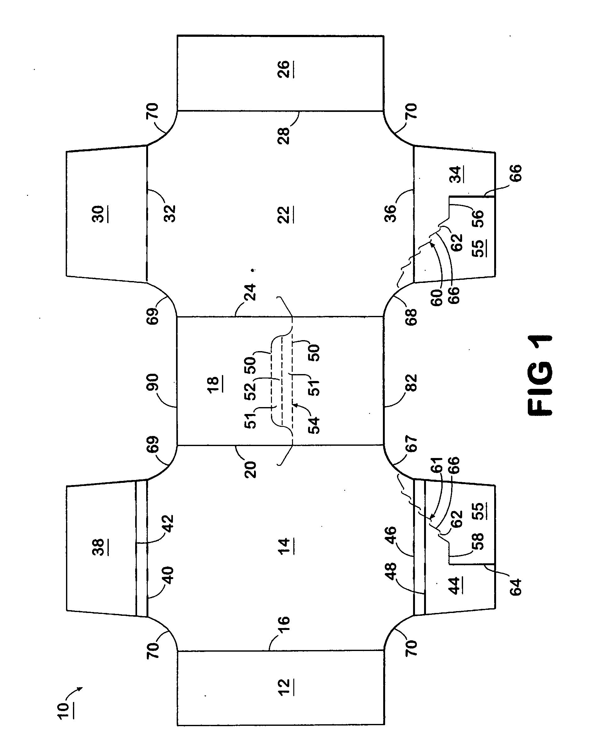
[0027] According to a preferred embodiment of the invention, the cans are packaged in a carton that is fully enclosed, except for openings in both ends at the top and bottom. The blank for forming this carton is illustrated in FIG. 1. The blank 10 is formed from a foldable sheet of material, such as paperboard. The blank 10 has a bottom flap 12 that is foldable connected to a bottom side panel 14 by fold line 16, and in turn connected to top panel 18 by fold line 20. The top panel 18 is connected to top side panel 22 by fold line 24, which in turn is connected to bottom flap 26 by fold line 28.

[0028] The blank 10 has a top side panel 22 that is connected to end flap 30 by fold line 32, and in turn connected to exiting end flap 34 by fold line 36. Bottom side panel 14 is connected to end flap 38 by fold lines 40 and 42, and ...


PUM

PropertyMeasurementUnit
Areaaaaaaaaaaa
Folded conformationaaaaaaaaaa

Abstract

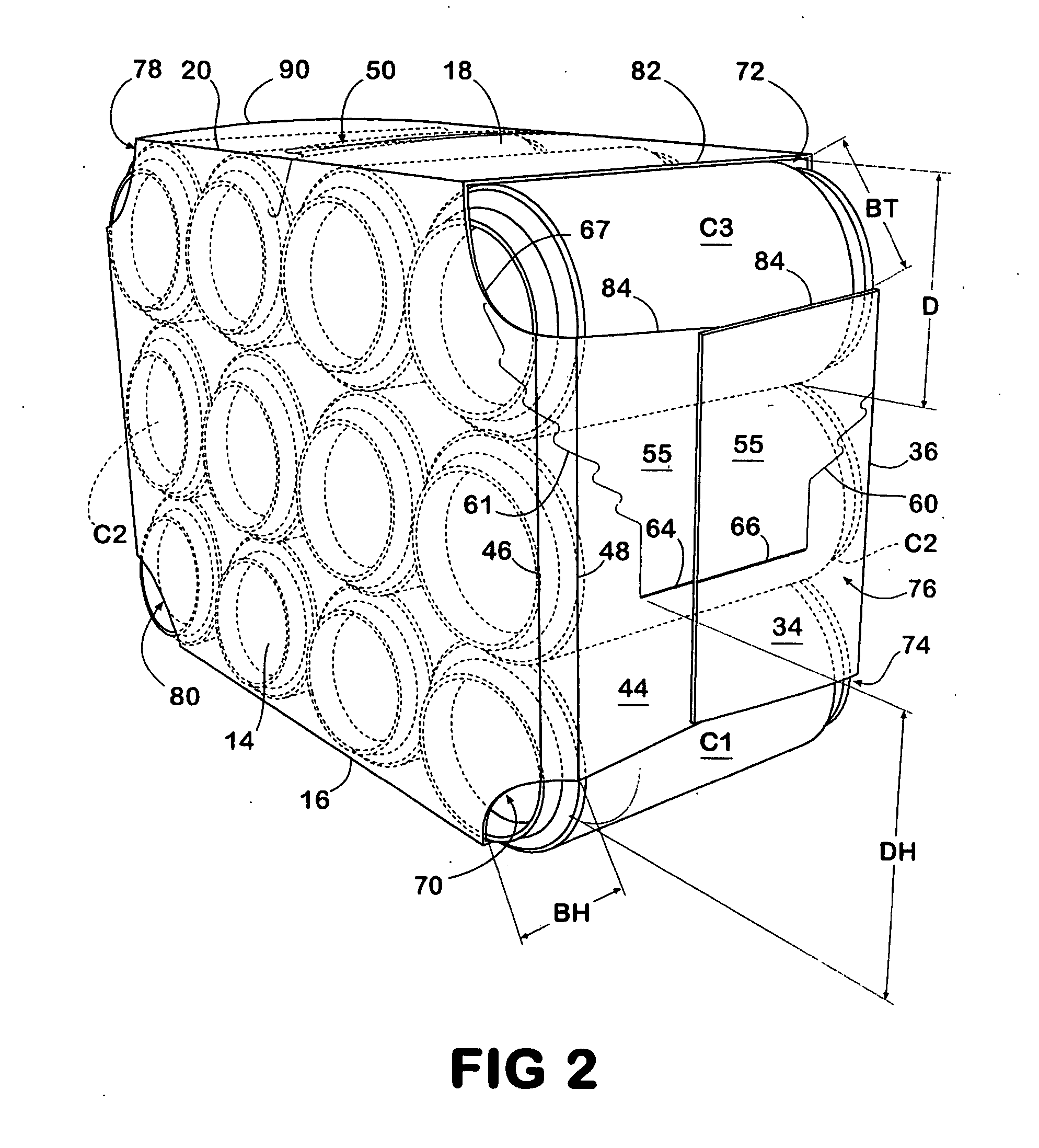
The carton is provided for carrying cylindrical containers, such as cans in three or more layers and having open ends at the top and bottom of each end of the carton. A dispenser flap is formed by zigzag tear lines in the exiting end of the carton. The carton is constructed so that the ends of a can adjacent the exiting end of the carton are exposed and can be grasped by a person pulling the can forward or up and commencing the tear line forming the flap. Preferable this tear line is of a zigzag configuration, or step format with interruptions in the riser. Cut tear lines in the step permit the controlled tearing of the tear line.

Description


Claims


Application Information

Patent Timeline
Owner GRAPHIC PACKAGING INT
Learn More