
Gas sample conditioning system

a gas sample and conditioning system technology, applied in the field of collecting and analyzing, can solve the problems of inability to purchase gas for resale, inability to accurately measure, and increase the cost of analyzer/chromatograph, so as to reduce the inherent risk attendant, improve the efficiency of gas line sample insertion, and reduce the effect of profil

Active Publication Date: 2006-01-05
MUSTANG SAMPLING
View PDF10 Cites 65 Cited by
  • Summary
  • Abstract
  • Description
  • Claims
  • Application Information

AI Technical Summary

Benefits of technology

[0027] Other objects of the invention are satisfied by a structure and method that provides for purging gas line tubing of air to enhance gas line sample insertion efficiencies.
[0028] Still further objects of the invention are satisfied by reducing the inherent risk attendant in hazardous environments and providing a minimal profile while matching or exceeding the performance of larger and more expensive systems.
[0029] The present invention also satisfies additional objects by providing structures and methods for gas sample thermal conditioning for analysis with optimized capabilities and minimal cost of operation.

Problems solved by technology

Post-regulation, however, pipeline companies no longer purchase gas for resale.
When this happens, the analyzer / chromatograph can potentially be seriously damaged because chromatograph devices ideally operate on dry input gases.
This downtime results in higher costs and inaccurate measurements.
Natural gas sampling systems, however, are typically located in harsh environments, e.g., where outdoor ambient temperatures can be significantly below the gas dew point temperature and where dangerous explosion-prone gas vapors are often permeating into the surrounding atmosphere.
Several problems are known to exist with prior art gas sample heating systems.
Obviously, exposing the hydrocarbon vapors in and around the sampling system to a spark potentially created by 12 volt car battery is not a desirable situation, e.g., due to the high risk of explosion.
Other related art systems, e.g., catalytic heaters adapted to operate by burning stored natural gas, are not economical and suffer from an increased operating expense, particularly under present market conditions.
Another, perhaps more significant, issue with conventional sample heater systems is the failure rate of such systems.
Because failure rates of typical conventional systems are at unacceptably high levels, the reliability of the sample testing systems have become problematic.

Method used


Image

  • Gas sample conditioning system
  • Gas sample conditioning system
  • Gas sample conditioning system

Examples


Embodiment Construction

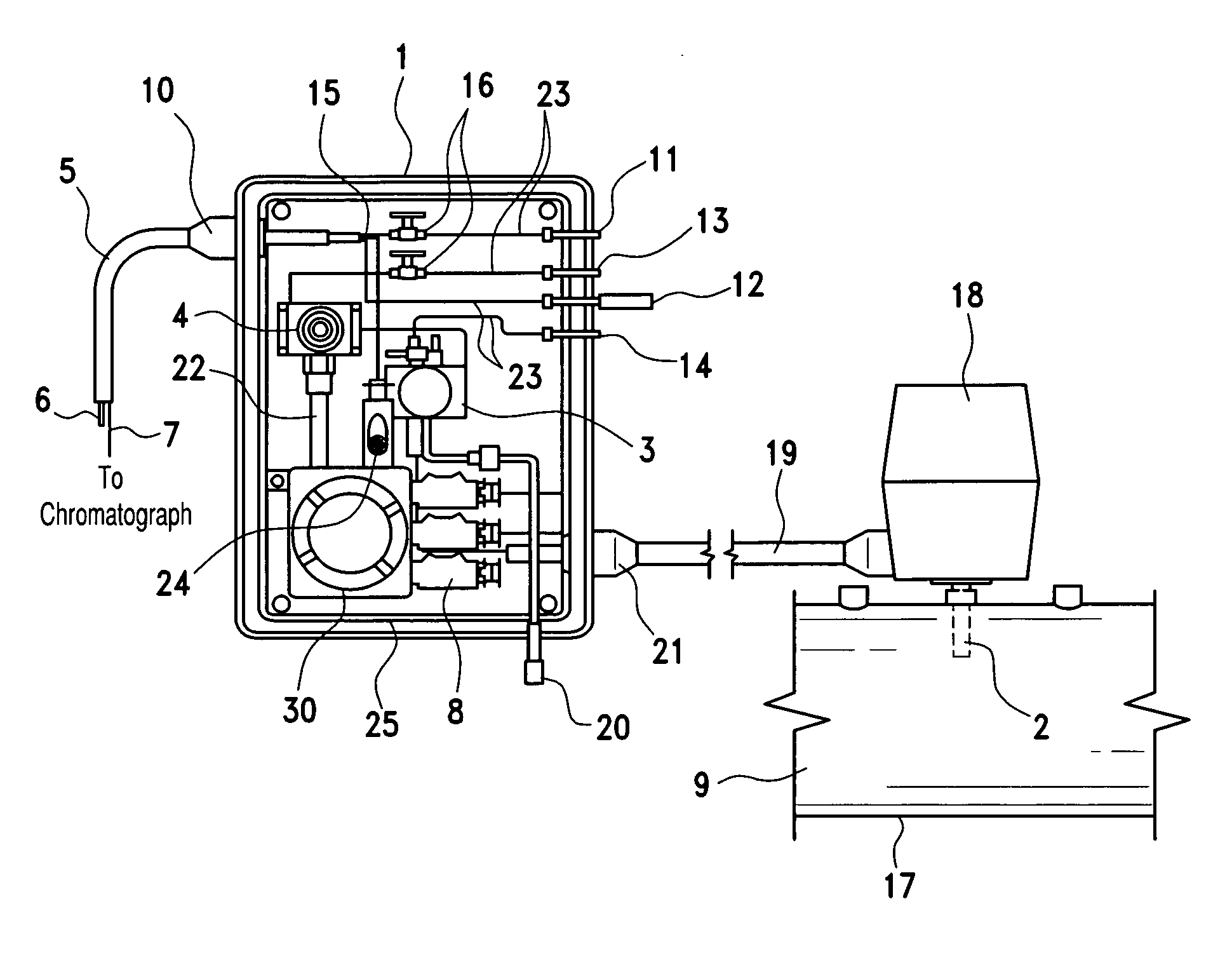
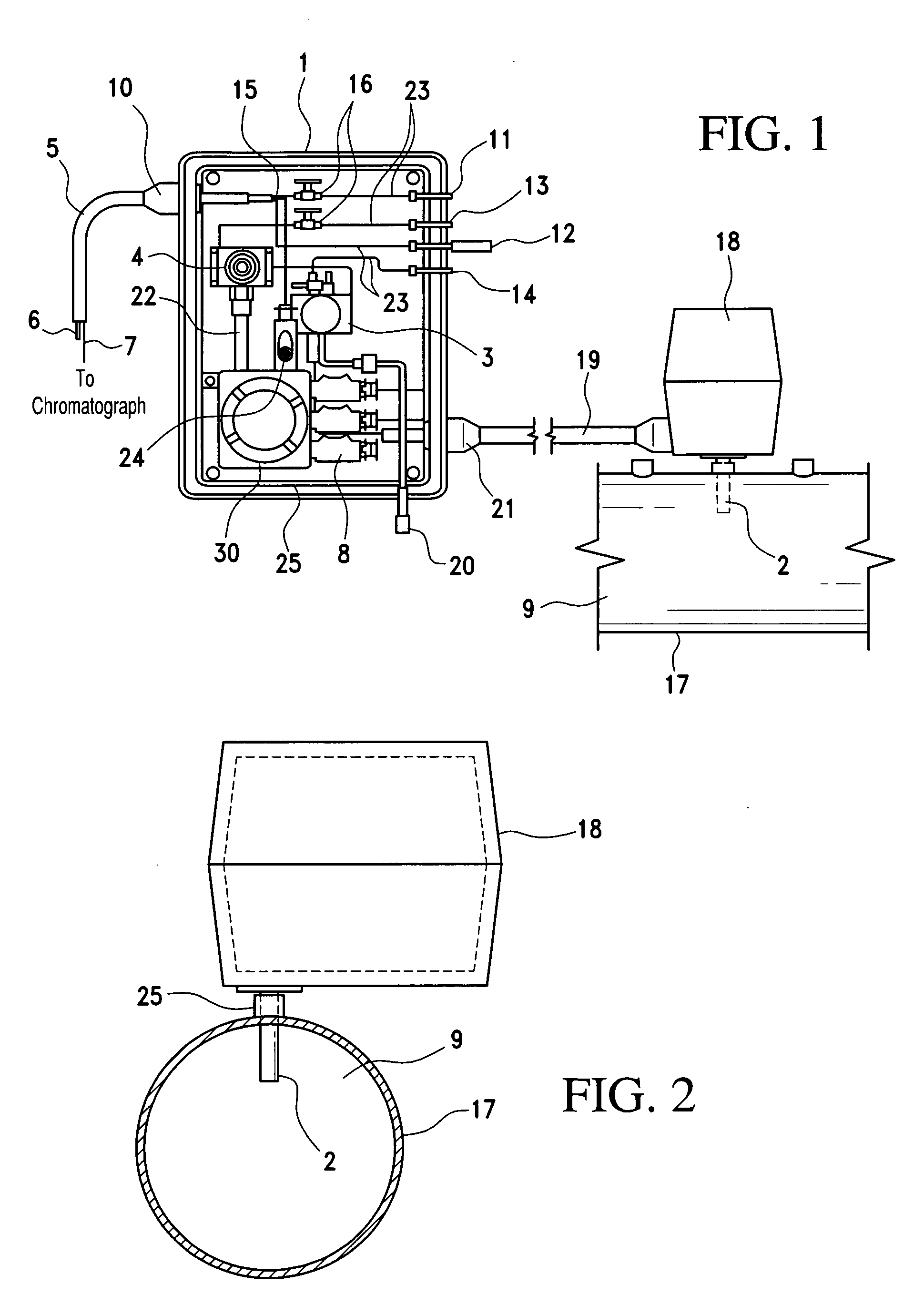
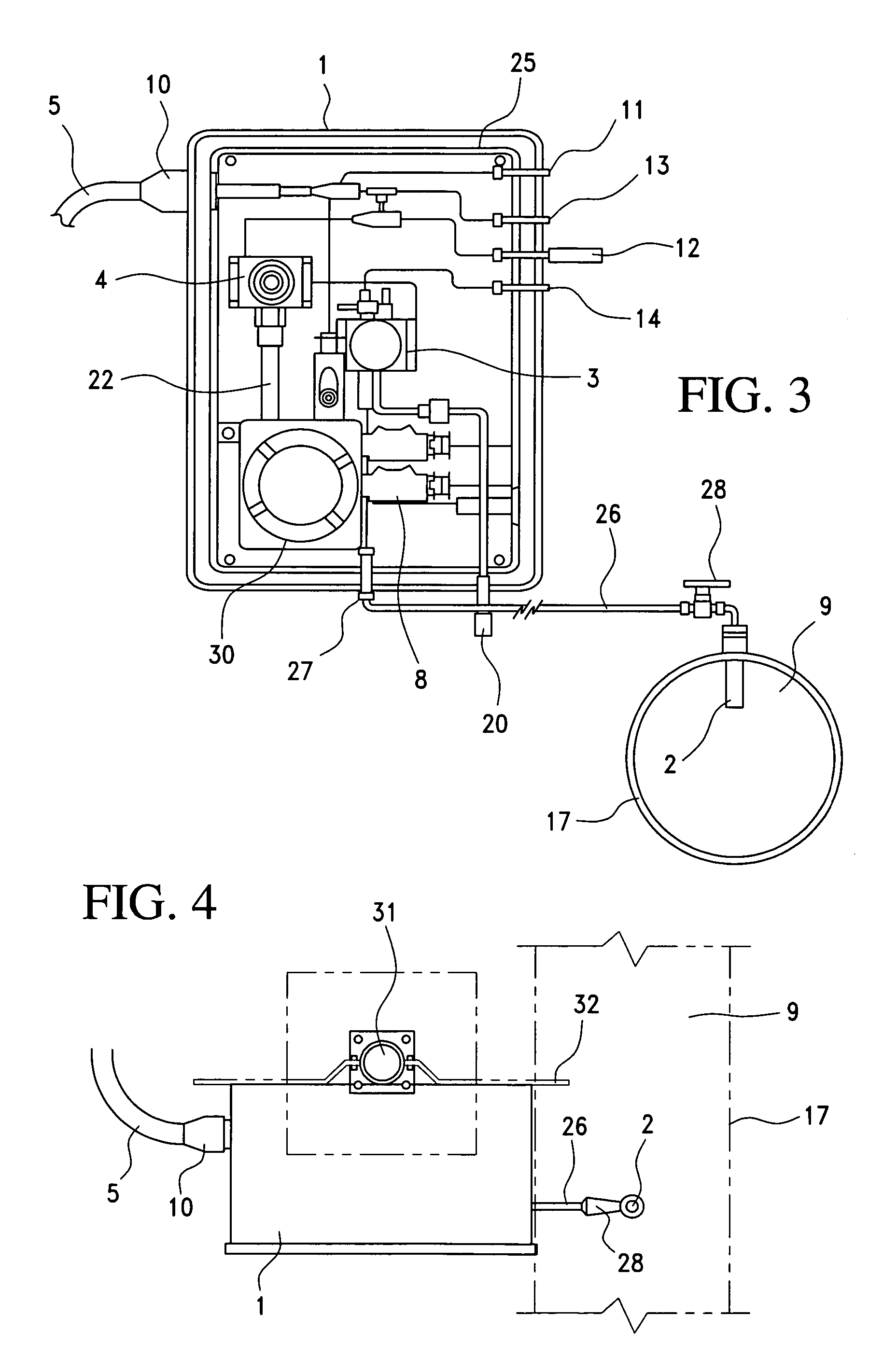
[0046] Exemplary, non-limiting, embodiments of the present invention are discussed in detail below. While specific configurations and dimensions are discussed to provide a clear understanding, it should be understood that the disclosed dimensions and configurations are provided for illustration purposes only. A person skilled in the relevant art will recognize that other dimensions and configurations may be used without departing from the spirit and scope of the invention.

[0047]FIG. 1 illustrates a system in accordance with the present invention. As shown, the system of FIG. 1 comprises a cabinet 1 having, for example, a generally rectangular configuration. The cabinet shown in this embodiment can be composed of polymeric resin, stainless steel, or any other appropriate material or combination of materials, e.g., aluminum panels etc., that provide a substantially strong housing. Further, a cabinet suitable for housing a system in accordance with the present invention is sufficientl...


PUM


Abstract

A gas sample and conditioning device for sampling gas in a storage or transport device and conditioning the gas to avoid dew point dropout of the gas. A chamber for regulating the temperature and the pressure of the gas is provided with external A.C. or D.C. power using the leads of existing heat tracing cables to avoid the need for additional power sources to power the temperature and pressure regulating devices within the chamber.

Description

CROSS REFERENCE TO RELATED APPLICATIONS [0001] This application is an application filed under 35 U.S.C. § 111(a) claiming benefit pursuant to 35 U.S.C. § 119(e)(1) of Provisional Application Ser. No. 60 / 583,792, filed on Jun. 30, 2004, pursuant to 35 U.S.C. § 111(b), the entire content of which is incorporated herein by reference.FIELD OF THE INVENTION [0002] This invention relates generally to collecting and conditioning samples of compositions in gaseous form. More particularly, the invention relates to thermal conditioning of pipeline samples from natural gas pipelines. BACKGROUND OF THE INVENTION [0003] Natural gas is a combustible, gaseous mixture of several different hydrocarbon compounds and is typically extracted from deep underground reservoirs formed by porous rock. The composition of natural gas extracted from different reservoirs varies depending on the geographic location of the reservoir. In fact, it is not entirely uncommon for the composition of gas extracted from a ...

Claims


Application Information

Patent Timeline
IPC IPC(8): G01N1/22
CPCG01N1/2214G01N1/2247G01N2001/2267G01N30/30G01N30/20
Inventor THOMPSON, KENNETH O.GERHOLD, WALTER F.
Owner MUSTANG SAMPLING
Learn More