
Battery pack assembly

a battery pack and assembly technology, applied in the direction of secondary cell servicing/maintenance, cell component details, cell components, etc., can solve the problems of complex system of rechargeable battery packs, the size and cost of electronic devices are rapidly decreasing, and the size of the device is so small

Inactive Publication Date: 2005-12-08
MOTOROLA INC
View PDF6 Cites 86 Cited by
  • Summary
  • Abstract
  • Description
  • Claims
  • Application Information

AI Technical Summary

Problems solved by technology

In reality, rechargeable battery packs are complex systems incorporating numerous components, including cells, protection circuitry, charging circuitry, and mechanical components.
Both the size and cost of electronic devices are rapidly decreasing.
In today's modern devices, like cellular telephones, radios and laptop computers, the size of the device has become so small that a large portion of the volume of the host device is occupied by the battery pack.
Additionally, the cost of the battery pack can rival the cost of the host device.
Due to this reduction in the overall size of electronic devices, there is pressure on battery designers to reduce the overall dimensions of battery packs.
This solution presents two problems: First, host devices must be designed to accommodate a particular battery pack.
Consequently, the device is unable to take advantage of new battery designs or technologies because the host device's internal circuitry is tailored only to one battery pack.
The second issue is reliability.
If the circuitry is removed from the battery pack, certain external conditions may compromise reliability of the battery pack.
If this circuitry is removed, battery reliability may be compromised if the terminals are accidentally shorted while the battery is not coupled to the host device.

Method used


Image

  • Battery pack assembly
  • Battery pack assembly
  • Battery pack assembly

Examples


Embodiment Construction

[0019] A preferred embodiment of the invention is now described in detail. Referring to the drawings, like numbers indicate like parts throughout the views. As used in the description herein and throughout the claims, the following terms take the meanings explicitly associated herein, unless the context clearly dictates otherwise: the meaning of “a,”“an,” and “the” includes plural reference, the meaning of “in” includes “in” and “on.”

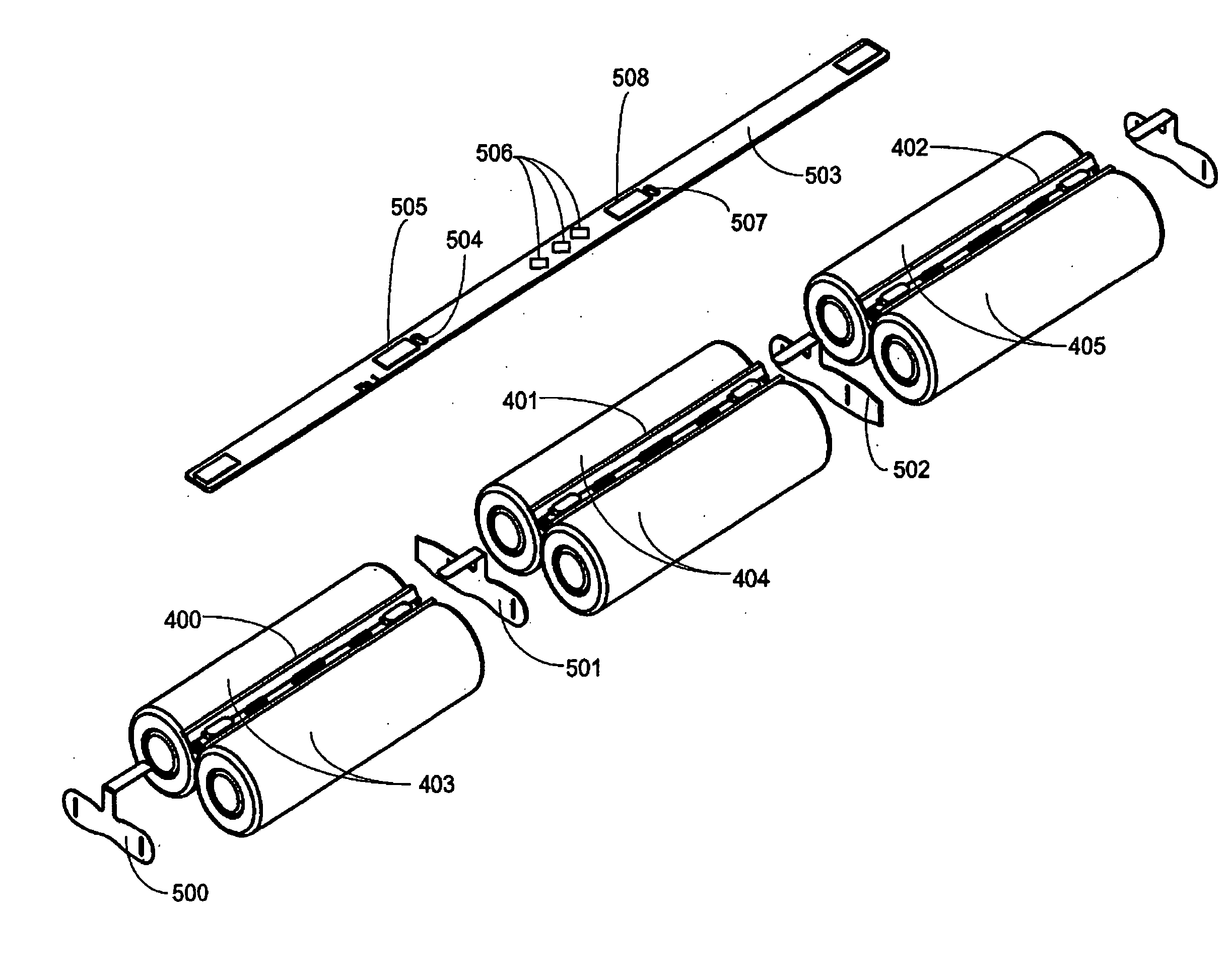
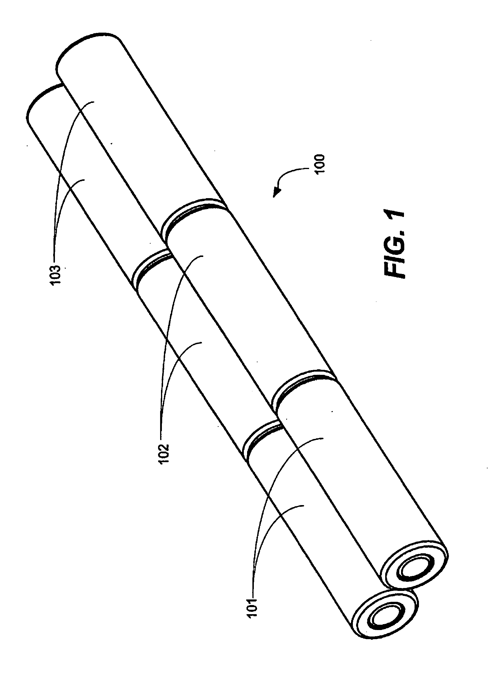
[0020] One preferred embodiment of this invention is a low-profile battery pack capable of bringing multiple cell connections from a plurality of rechargeable, electrochemical cells to an external connector on the outside of the battery pack, while providing an electrolyte barrier between the cells and the external connector. When electrochemical cells malfunction, they occasionally release liquid electrolyte. The electrolyte barrier ensures that any liquid electrolyte that is released within the pack is isolated from the main circuit board and external...


PUM

PropertyMeasurementUnit
radiiaaaaaaaaaa
insulatoraaaaaaaaaa
flexibleaaaaaaaaaa

Abstract

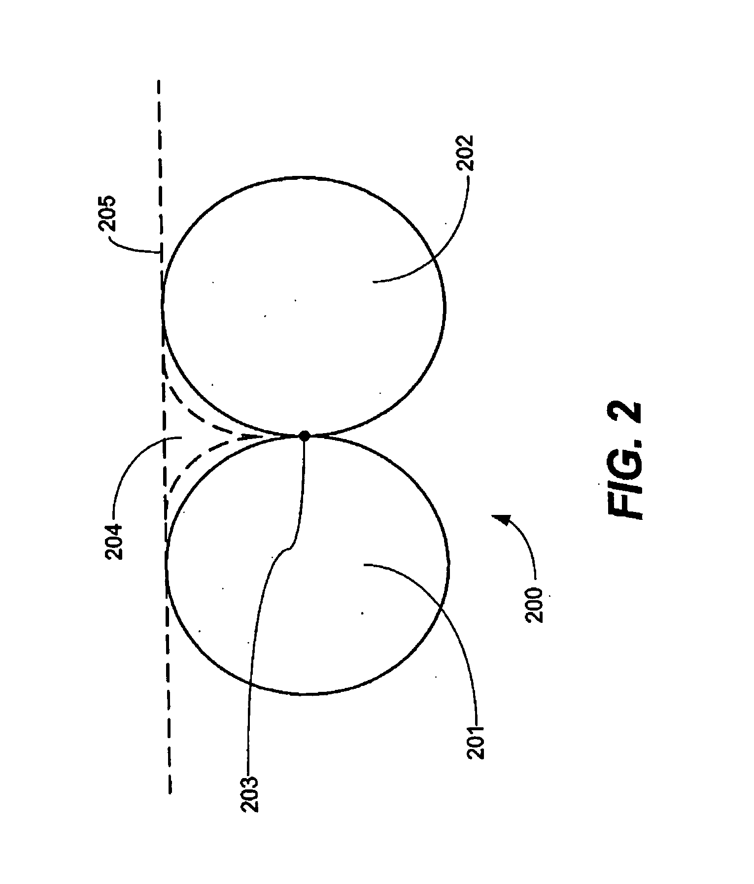
A low-profile battery pack having an electrolyte barrier is provided. The pack includes a plurality of rechargeable cells, being arranged in end to end pairs of two cells. A cleavage void formed by the convex geometry of the cells accommodates at least one insulator and a first circuit board. Tabs couple the cells to the first circuit board. A flexible substrate couples the first circuit board to a second circuit board. The assembly is then placed in a housing having a first compartment and a second compartment, such that the cells are placed in the first compartment and the second circuit board is placed in the second compartment. Between the first and second compartments exists an electrolyte barrier. The flexible substrate passes through an opening in the electrolyte barrier. Adhesive placed in the opening, about the flexible substrate, ensures a seal that keeps electrolyte that may appear in the first chamber from passing to the second chamber. The overall battery pack is both compact in size and robust in performance.

Description

BACKGROUND [0001] 1. Technical Field [0002] This invention relates generally to rechargeable battery packs, and more specifically to a low-profile battery pack assembly having electrical and mechanical components arranged so as to reduce overall battery pack size and increase reliability. [0003] 2. Background Art [0004] Some people think that a rechargeable battery pack is simply a rechargeable electrochemical cell wrapped in plastic. In reality, rechargeable battery packs are complex systems incorporating numerous components, including cells, protection circuitry, charging circuitry, and mechanical components. These components work in harmony to deliver safe, reliable power to portable electronic devices. [0005] Both the size and cost of electronic devices are rapidly decreasing. In today's modern devices, like cellular telephones, radios and laptop computers, the size of the device has become so small that a large portion of the volume of the host device is occupied by the battery...

Claims


Application Information

Patent Timeline
Patent Type & Authority Applications(United States)
IPC IPC(8): H01M10/42H01M50/519H01M50/529
CPCH01M2/105H01M2/1055H01M2/204H01M10/425Y02E60/10H01M50/213H01M50/519
Inventor KIGER, WILLIAM B.MAGGERT, KEVIN K.
Owner MOTOROLA INC
Learn More