
Child restraint system for a vehicle seat

a child restraint and vehicle seat technology, applied in the direction of vehicular safety arrangements, pedestrian/occupant safety arrangements, transportation and packaging, etc., can solve the problems of ineffective or unsafe use of three-point seat belt systems installed in vehicles by the original manufacturer, and special problems regarding the integration of active restraint seat belt systems

Inactive Publication Date: 2005-12-08
INDIANA MILLS MFG
View PDF40 Cites 19 Cited by
  • Summary
  • Abstract
  • Description
  • Claims
  • Application Information

AI Technical Summary

Benefits of technology

The patent describes a modular vehicle seat that can be easily mounted to a vehicle's frame and has a seat back that can move away from the seat in case of an accident. The seat can also have a seat base that can move downward to form a child seat. The technical effects of this invention are that it provides a flexible and customizable seat that can be easily adjusted for different needs and comfort levels, and also ensures safety during accidents.

Problems solved by technology

Vehicles with deforming or deflecting seats provide special problems regarding the integration of active restraint seat belt systems.
Three-point seat belt systems installed in vehicles by the original manufacturer may be ineffective or unsafe when used by, for example, infants, children, or those with physical handicaps.

Method used


Image

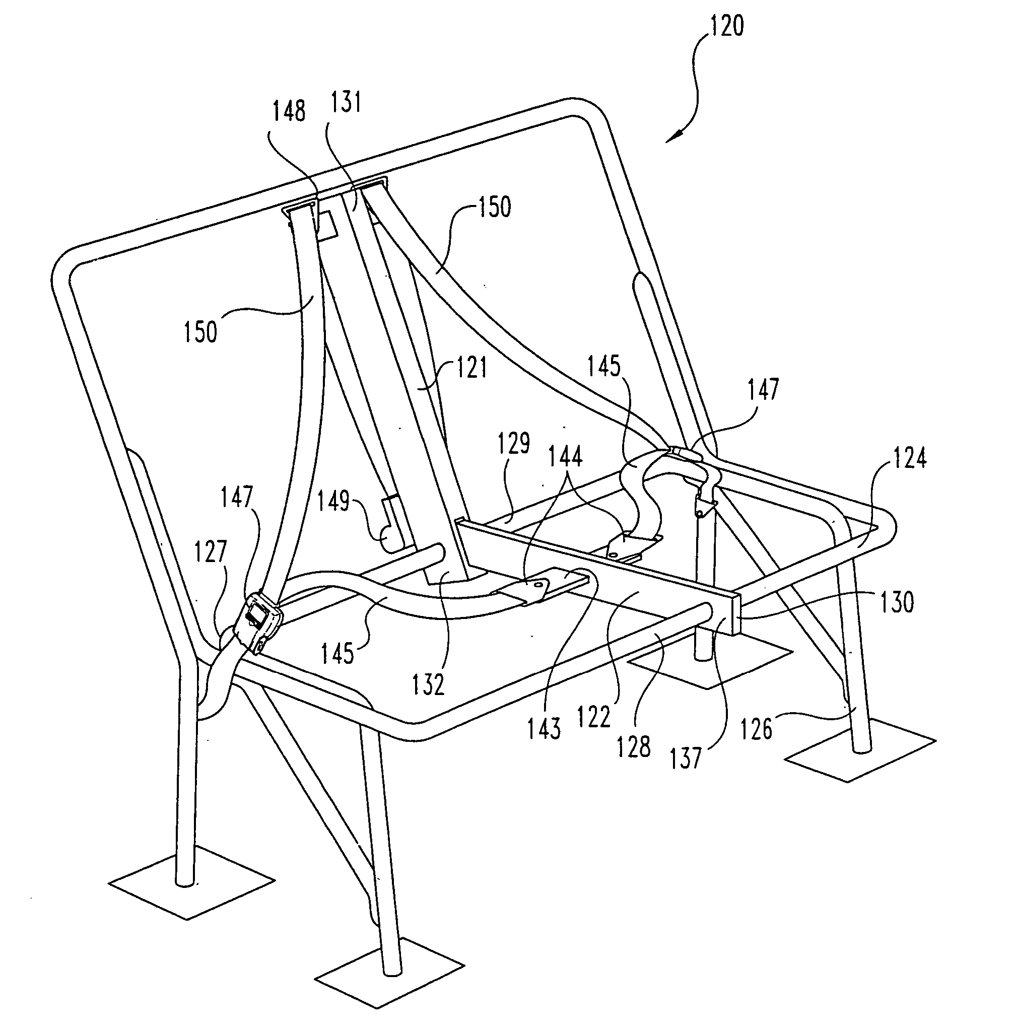
  • Child restraint system for a vehicle seat
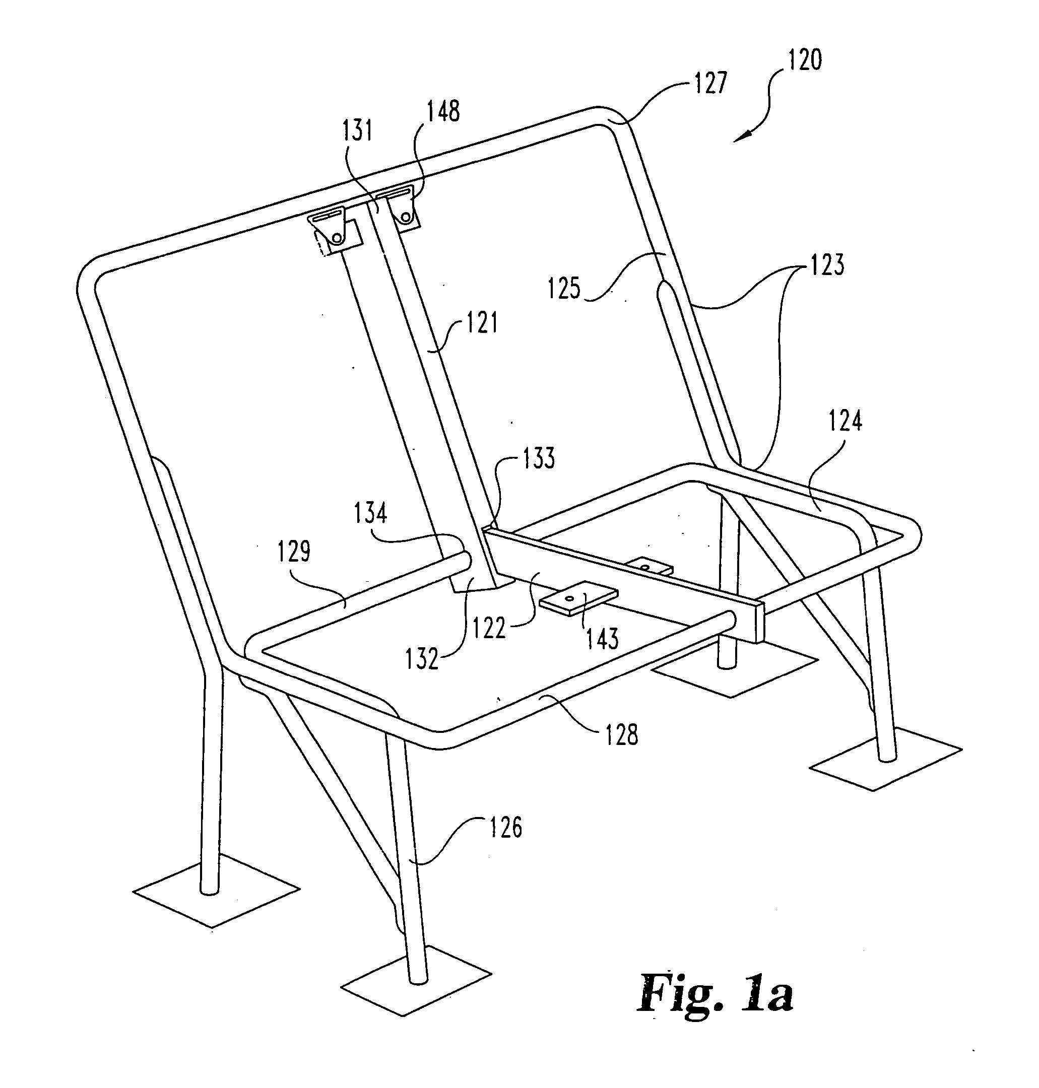
  • Child restraint system for a vehicle seat
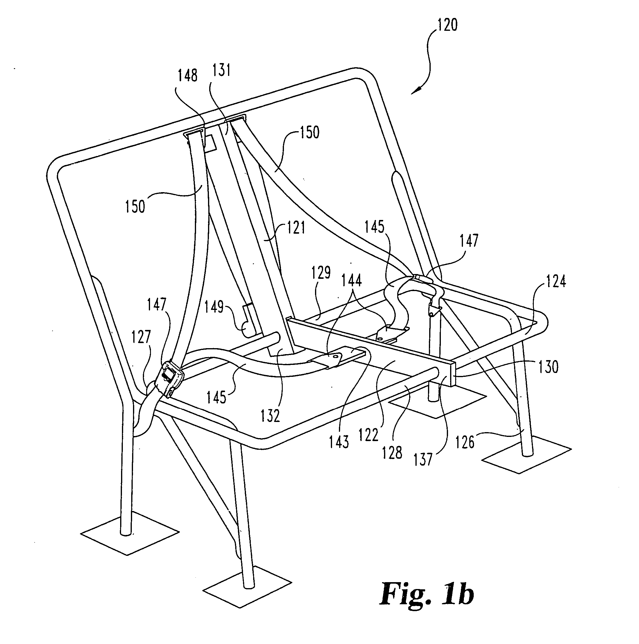
  • Child restraint system for a vehicle seat

Examples


Embodiment Construction

[0069] For the purposes of promoting an understanding of the principles of the invention, reference will now be made to the embodiments illustrated in the drawings and specific language will be used to describe the same. It will nevertheless be understood that no limitation of the scope of the invention is thereby intended, such alterations and further modifications in the illustrated device, and such further applications of the principles of the invention as illustrated therein being contemplated as would normally occur to one skilled in the art to which the invention relates.

[0070] Referring now more particularly to the drawings, FIGS. 1 through 3 show a three-point restraint system 120 incorporating a first and illustrative embodiment of the present invention. The restraint system 120 is designed to restrain two passengers sitting side by side: The restraint system 120 includes a tower member 121 movably coupled to a connecting member 122, and is adapted to be mounted to a conve...


PUM


Abstract

A passenger vehicle seat and restraint system comprising a frame mountable to a vehicle and a restraint member and a seat member coupled to the frame to form a seat for supporting an occupant. The vehicle seat may further comprise a seat back frame movably attached to the frame and a restraint harness affixed to the frame and the seat back frame for securing the occupant thereto.

Description

CROSS-REFERENCE TO RELATED APPLICATIONS [0001] This application is a continuation-in-part of co-pending U.S. patent application Ser. No. 09 / 734,361, filed Dec. 11, 2000, and titled Restraint System for a School Bus Seat, now U.S. Pat. No. ______, which is a continuation of U.S. patent application Ser. No. 09 / 479,197, filed Jan. 7, 2000, which in turn is a continuation-in-part of U.S. Ser. No. 09 / 183,088 filed Oct. 30, 1998, and titled Restraint System for a School Bus Seat, now U.S. Pat. No. 6,123,388, all of which are hereby incorporated herein by reference. This application claims the benefit of and priority to U.S. Provisional Patent Application Serial No. 60 / 362,203, filed Mar. 5, 2002, and titled Child Restraint System, the disclosure of which is also hereby incorporated herein by reference.FIELD OF THE INVENTION [0002] The present invention is in the field of passenger restraint systems used to provide a protective passenger environment DESCRIPTION OF THE PRIOR ART [0003] Conv...

Claims


Application Information

Patent Timeline
Patent Type & Authority Applications(United States)
IPC IPC(8): B60N2/24B60N2/68
CPCB60N2/688B60N2/242
Inventor VITS, CHARLES G.FOYE, CHRISTOPHER W.GRAY, LARRY E.BOYLE, DONALD C.SCELSI, JOHN DAVID
Owner INDIANA MILLS MFG
Learn More