Wavelength division multiplexing add/drop system employing optical switches and interleavers
a technology of optical switches and interleavers, applied in the field of design and manufacturing of multiple wavelength add/drop systems, can solve problems such as channel cross-talk, channel cross-talk, and/or (b) unnecessary power loss among neighboring channels
- Summary
- Abstract
- Description
- Claims
- Application Information
AI Technical Summary
Problems solved by technology
Method used
Image
Examples
first embodiment
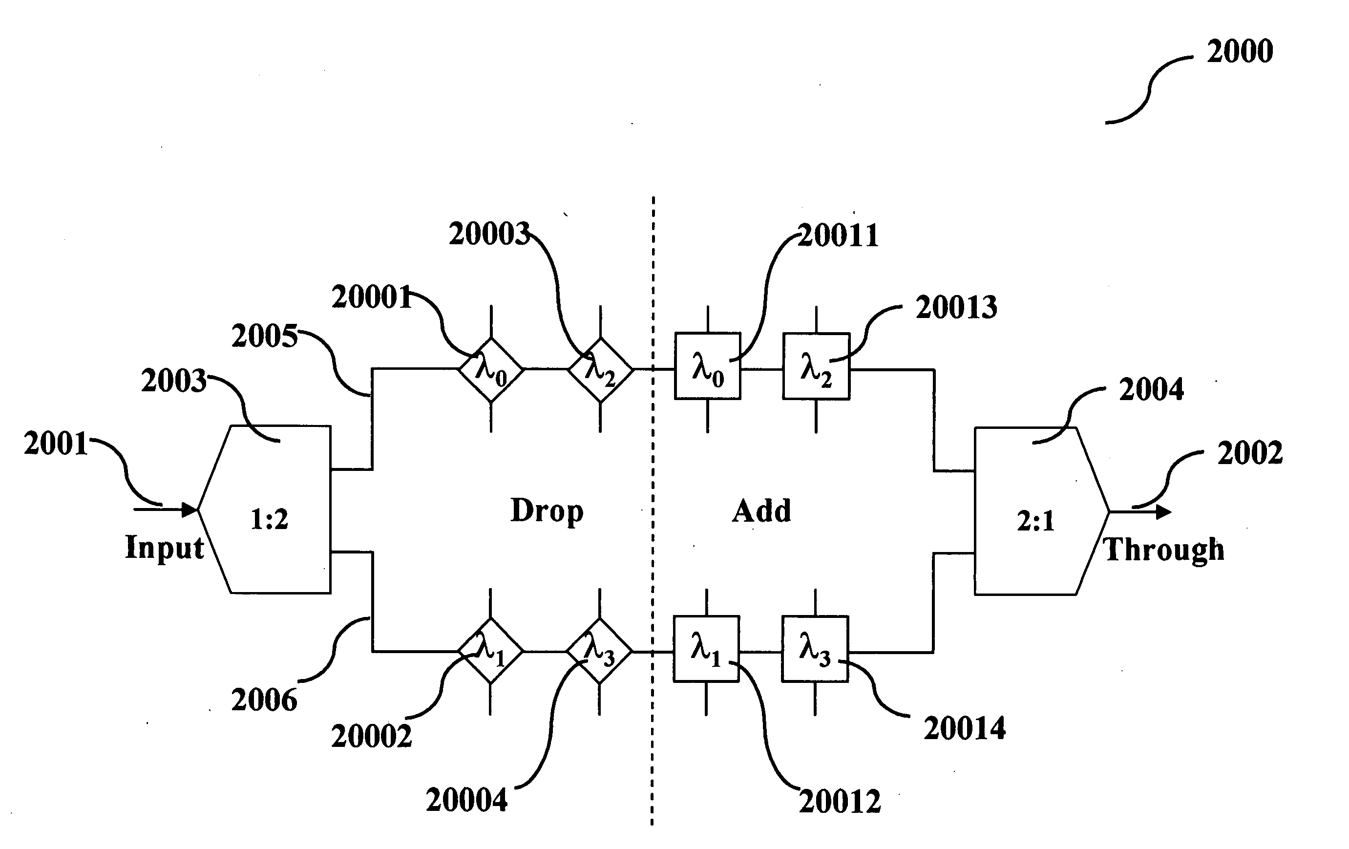
[0077] To generalize, this invention relates to the design of an N-channel OADM utilizing:
[0078] (1) two 1:M optical wavelength interleavers,
[0079] (2) M optical paths,
[0080] (3) P (where P times M is greater than or equal to N) wavelength selective “add” optical switches, and
[0081] (4) the same number of wavelength selective “drop” optical switches on each path.
[0082] FIGS. 12A˜12C and 13 illustrate the case when N=4 and M=2, and FIGS. 15A˜15C and 16 illustrate the case when N=8 and M=4. These are merely illustrative examples and the contemplated combinations are nearly endless for an N-channel OADM based on this method. In each design, signal degradation due to propagation loss and optical switches are reduced by a factor of M compared to the conventional design. This embodiment is advantageous, therefore, in cases where this factor-of-M reduction outweighs signal degradation due to the two interleavers.
[0083] The architecture above can be adapted to use combination add / drop ...
second embodiment
[0093] To generalize, this invention relates to the design of an N-channel OADM utilizing
[0094] (1) two 1:M optical wavelength interleavers,
[0095] (2) M optical paths,
[0096] (3) P (where P times M is greater than or equal to N) wavelength selective “add / drop” optical switches, on each path.
[0097] FIGS. 18A˜18C and 19 illustrate the case when N=4 and M=2, and FIGS. 20A˜20C and 21 illustrate the case when N=8 and M=4. These are merely illustrative examples and the contemplated combinations are nearly endless for an N-channel OADM based on this method. In each design, signal degradation due to propagation loss and optical switches are reduced by a factor of M compared to the conventional design. This embodiment is advantageous, therefore, in cases where this factor-of-M reduction outweighs signal degradation due to the two interleavers.
[0098] The architecture described above can be adapted to use wavelength selective reflective optical switch as shown in FIG. 22. The thin outline o...
third embodiment
[0108] To generalize, this invention relates to the design of an N-channel optical “drop” multiplexer utilizing:
[0109] (1) two 1:M optical wavelength interleavers,
[0110] (2) M optical paths,
[0111] (3) one optical circulator, and
[0112] (4) P (where P times M is greater than or equal to N) wavelength selective reflective optical devices on each path.
[0113] FIGS. 24A˜24C and 25 illustrate the case when N=4 and M=2, and FIGS. 26A˜26C and 27 illustrate the case when N=8 and M=4. These are merely illustrative examples and the contemplated combinations are nearly endless for an N-channel OADM based on this method. In each design, signal degradation due to propagation loss and optical multiplexers are reduced by a factor of M compared to the conventional design. This embodiment is advantageous, therefore, in cases where this factor-of-M reduction outweighs signal degradation due to the two interleavers.
[0114]FIG. 28A shows a schematic of an optical wavelength blocker. It consists of wa...
PUM
 Abstract
Description
Claims
Application Information
 - R&D
- Intellectual Property
- Life Sciences
- Materials
- Tech Scout
- Unparalleled Data Quality
- Higher Quality Content
- 60% Fewer Hallucinations
Browse by: Latest US Patents, China's latest patents, Technical Efficacy Thesaurus, Application Domain, Technology Topic, Popular Technical Reports.
© 2025 PatSnap. All rights reserved.Legal|Privacy policy|Modern Slavery Act Transparency Statement|Sitemap|About US| Contact US: help@patsnap.com


