
Optical fiber pH sensor

a technology of optical fiber and ph sensor, applied in the field of optical fiber ph sensor, can solve the problems of human and environment safety risks, high maintenance costs, and certain drawbacks in the detection of metallic corrosion in difficult access equipment and installations

Active Publication Date: 2005-12-01
PETROLEO BRASILEIRO SA (PETROBRAS)
View PDF5 Cites 47 Cited by
  • Summary
  • Abstract
  • Description
  • Claims
  • Application Information

AI Technical Summary

Benefits of technology

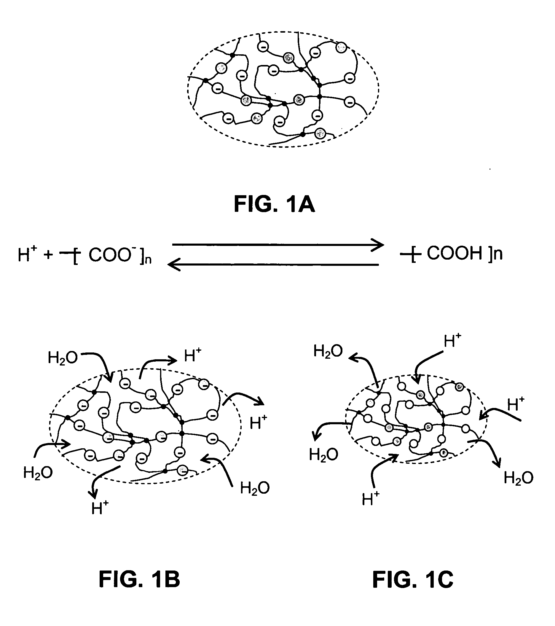
The present invention is about a pH sensor that uses an optical fiber to measure the pH of aqueous solutions. The sensor consists of a rigid housing with two compartments separated by a device. The first compartment contains a set of discs made up of a pH-sensitive hydrogel, while the second compartment has an optical fiber with a Bragg grating. The hydrogel changes its volume when exposed to pH changes, which causes a strain on the Bragg grating, which in turn alters the wavelength of the grating. This change is measured using any usual wavelength measurement technique. The invention provides a pH sensor that can be placed in a well, pipes, and difficult access equipment to measure pH together with other sensors such as downhole pressure, temperature, and flow rate. It also allows for the indirect evaluation of corrosion rate and can sweep a wide range of pH values by using different hydrogels in the set of polymer discs. Additionally, it can be placed in series with another sensor containing a different hydrogel that is sensitive to a different pH range while utilizing the same optical fiber.

Problems solved by technology

On the other hand, certain drawbacks in the detection of metallic corrosion in difficult access equipment and installations have not yet been solved in the several industrial fields.
In the petroleum industry, metallic corrosion can cause the premature failure of equipments as well as oil leaks, leading to human and environment safety risk and with expensive maintenance operations.

Method used


Image

  • Optical fiber pH sensor
  • Optical fiber pH sensor
  • Optical fiber pH sensor

Examples


Embodiment Construction

[0042] As previously described, the optical fiber pH sensor of the invention for the measurement of pH utilizes a transducer that mechanically couples an optical fiber containing a Bragg grating, to a pH-sensitive hydrogel.

[0043] The concept of the present invention is therefore based on the fact that the mechanical features as well as the pH sensitivity of a hydrogel combined to a mechanical device making compatible the stress-strain properties of the said device with those of an optical fiber containing a Bragg grating allows recovering the information of the pH value of an aqueous solution to the optical domain, yielding a fiber Bragg grating pH sensor.

[0044] For the purposes of the invention, a useful hydrogel is any hydrogel sensitive to the pH range that one desires to measure. Thus, the inventive sensor is not limited to a specific hydrogel, on the contrary, it contemplates the use of several hydrogels, which can be sensitive to wide pH ranges since around 2.0 and up to aro...


PUM

PropertyMeasurementUnit
wavelength λBaaaaaaaaaa
wavelength measurementaaaaaaaaaa

Abstract

An optical fiber pH sensor 100, 200, 300 is described, where a transducer mechanically couples a Bragg grating to a pH-sensitive hydrogel, said sensor comprising a central part 110, 210, 301 where are placed the optical fiber 121 containing a Bragg grating 122, the pH-sensitive hydrogel set of discs 130, and the mechanical transducer which is a spring 123 a beam 215 or still the optical fiber itself 121, the mechanical transducer assuring the strain on the Bragg grating 122. The change in hydrogel hydrodynamic volume resulting from a change of the pH of the medium introduces a force that is sufficient to cause a strain in the Bragg grating. The measure of the pH change is retrieved using the usual techniques for wavelength measurement. The pH sensor 100, 200, 300 of the invention is useful for the indirect evaluation and control of corrosion in petroleum wells and is suitable for multiplexing with other optical fiber sensors measuring the same or different parameters.

Description

FIELD OF THE INVENTION [0001] The present invention relates to an optical fiber pH sensor designed for measuring the pH of aqueous solutions, where a transducer mechanically couples a Bragg grating to a pH-sensitive hydrogel, more specifically, to a pH sensor where the change of the hydrogel hydrodynamic volume resulting from a pH change in the medium causes a force which is large enough to strain the Bragg grating, the pH measurement being retrieved through usual techniques for wavelength measurement. BACKGROUND INFORMATION [0002] A Fiber Bragg Grating or FBG is a passive optical component obtained by imprinting a local, longitudinal and periodic modulation of the refractive index of the optical fiber core. In view of the local change of the refractive index, any light propagating along the fiber core undergoes partial reflection at each of the grating layers. As a consequence of the periodicity of the index modulation, constructive interference of the reflected light occurs for th...

Claims


Application Information

Patent Timeline
Patent Type & Authority Applications(United States)
IPC IPC(8): G01N21/45G01N21/77G01N21/80G02B6/00
CPCG01N21/45G01N2021/7723G01N21/80G01N21/774
Inventor DA SILVA, MANOEL FELICIANO JR.D'ALMEIDA, ARNALDO RODRIGUESRIBEIRO, FABIO PEREIRAVALENTE, LUIZ CARLOS GUEDESBRAGA, ARTHUR MARTINS BARBOSATRIQUES, ADRIANA LUCIA CERRI
Owner PETROLEO BRASILEIRO SA (PETROBRAS)
Learn More