
Portable storage container

Active Publication Date: 2005-12-01
REHRIG PACIFIC CO INC
View PDF50 Cites 33 Cited by
  • Summary
  • Abstract
  • Description
  • Claims
  • Application Information

AI Technical Summary

Benefits of technology

[0006] A container according to one embodiment of the present invention provides a low nest position and a high nest position for the bail members. In the low nest position, a container stacked thereon will nest into the container significantly, thereby minimizing the total space occupied by the two containers, while still providing a minimal clearance between the floors of the two containers for short goods stored in the lower container.
[0007] In the high nest position, a little more storage space is provided between the floors of the stacked / nested containers, such that larger goods can be stored in the lower container without contact from the upper container. In the high nest position, the bail member is oriented such that a support portion of the bail member spaced upwardly from uppermost edges of the walls. The bail member is outward of the walls of the container, thus permitting the floor and the walls of the upper container to nest significantly into the lower container. The bail member engages a ledge protruding outwardly from an outer surface of the wall of the upper container. For shorter goods that fit between the floors of the upper and lower containers, this provides a very efficient overall stacking height of the containers.
[0008] The bail members can also be moved to upper and lower stack positions, wherein the floor of the upper container is supported by the bail members at two different heights. The goods in the lower container are protected from contact by the upper container while providing an efficient overall stacking height of the upper and lower containers.
[0012] In one embodiment, an upward projection extending into the pin opening separates a first position and a second position of the pin. The pin is in the first position in the pin opening when the bail member is in the high nest position. The pin is in the second position in the pin opening when the bail member is in the low nest position. The upward projection assists in retaining the bail member in the high nest position.

Problems solved by technology

The depth at which the bail members can support a container stacked thereon is limited because structure for supporting the bail member must be provided and the structure must still be able to nest with a container nested thereon.
Providing bail members that extend substantially below the top band of the container can diminish stability and structural integrity.
Additionally, the longer the arms of the bail member are, the more likely they are to become misaligned.

Method used


Image

  • Portable storage container
  • Portable storage container
  • Portable storage container

Examples


Embodiment Construction

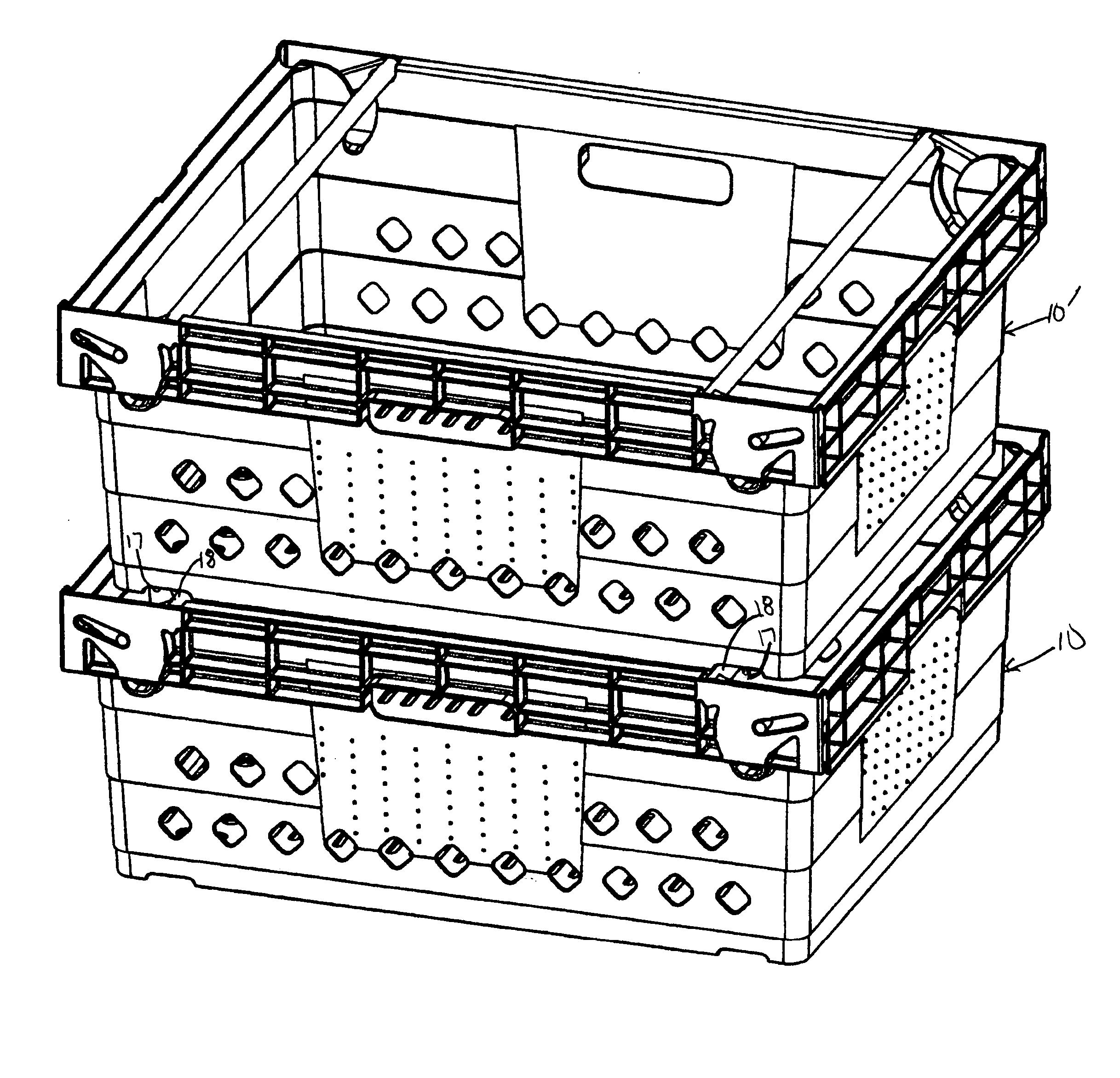
[0052] A container 10 according to the present invention is shown in FIG. 1. The container 10 includes a floor 12, a pair of opposed side walls 14 and a pair of opposed end walls 16. A pair of notches 17 are formed at the bottom of the end walls 16 and the floor 12. The notches 17 each define a channel which extends from one end wall 16 to the other.

[0053] Two bail members 18 are each mounted to each end wall 16. While they may take a variety of shapes, bail members 18 are shown having a generally cylindrical support portion 19 that extends across the length of the container 10. Each bail member 18 includes a pair of arms 21 extending transversely from the support portion 19. Near the intersection of each arm 21 with the support portion 19, a locking projection 22 protrudes from the support portion 19 and arm 21.

[0054] The end walls 16 each include an upper wall portion that has an outer wall portion 20 spaced from an inner wall portion 23. A lower wall portion 24 is generally ali...


PUM


Abstract

A portable storage container that both stacks and nests with similar containers includes a plurality of walls extending upwardly from a floor. At least one bail member is moveable between a plurality of positions for supporting the similar containers at varying heights. The bail member is moveable between a low nest position and a high nest position. In the low nest position, minimal clearance between the floors of the stacked containers is provided, and the stacked containers have the lowest overall height. In the high nest position, a ledge protruding outwardly from an outer surface of a wall of the upper container is supported on a support portion of the bail arm.

Description

CROSS-REFERENCE TO RELATED APPLICATION [0001] This application is a continuation in part of U.S. Ser. No. 10 / 854,378 filed May 25, 2004.BACKGROUND OF THE INVENTION [0002] The present invention relates generally to portable storage containers and more particularly to portable storage containers that provide the ability to select different nesting and stacking depths. [0003] Portable storage containers that both stack and nest with similar containers are commonly used for transporting and storing goods. Nesting is typically achieved when an empty container receives a like container therein such that there is at least some overlap between the walls of the containers. The stacking feature is typically used when an occupied container has a like container supported thereon, such that the goods contained in the lower container are preferably not contacted or damaged by the upper container. Many containers use members known bail members to achieve the stacking feature. Bail members may typi...

Claims


Application Information

Patent Timeline
IPC IPC(8): B65D21/06
CPCB65D21/062
Inventor HASSELL, JON P.APPS, WILLIAM P.DANNENFELDT, MATTHEW L.
Owner REHRIG PACIFIC CO INC
Learn More