Blower
a blower and blower technology, applied in the field of blowers, can solve the problems of poor ventilation efficiency and increase in noise, and achieve the effects of improving ventilation efficiency, increasing static pressure, and reducing nois
- Summary
- Abstract
- Description
- Claims
- Application Information
AI Technical Summary
Benefits of technology
Problems solved by technology
Method used
Image
Examples
embodiment 1
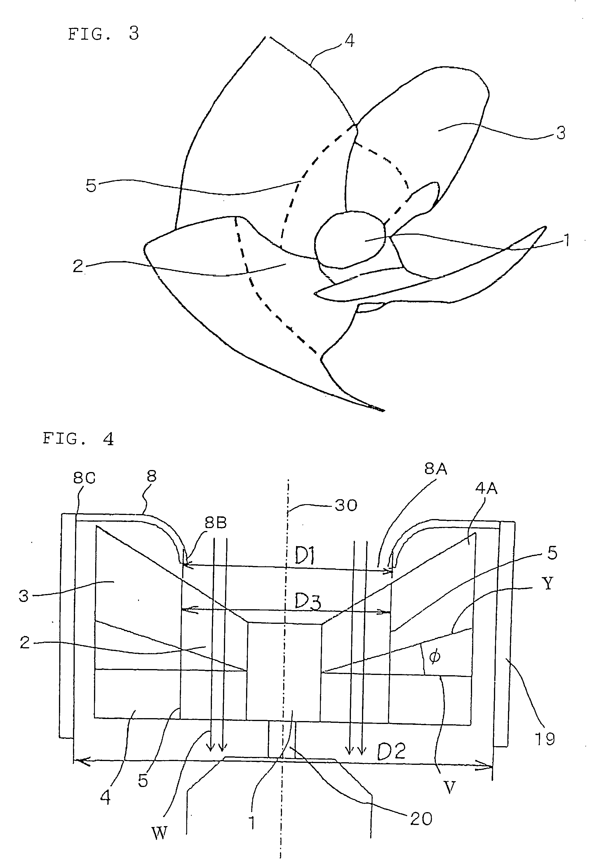
[0026]FIG. 1 is a front view of a blower according to Embodiment 1 of this invention as seen from the suction side thereof, FIG. 2 is a front view of the blower of FIG. 1 with a bell mouth 8 removed therefrom, FIG. 3 is a perspective view of blades 4 of the blower of FIG. 1, FIGS. 4 and 5 are sectional views taken along the line IV-IV of FIG. 1 when the blades 4 are rotating, and FIG. 6 is a sectional view taken along the line VI-VI of FIG. 5. FIG. 2 shows how the blades 4 are projected onto a plane perpendicular to a rotation axis 30 which is the center axis of a boss 1; it is a front view, as seen from the suction side, of a plane perpendicular to the rotation axis 30.
[0027] This blower is equipped with a motor shaft 20, a cylindrical boss 1 directly connected to the motor shaft 20 so as to be concentric therewith, four blades 4 mounted to the outer peripheral surface of the boss 1 circumferentially at equal intervals, a cylindrical case 19 surrounding the blades 4, and the bell ...
embodiment 2
[0063]FIG. 9 is a diagram for illustrating the construction of a blower according to Embodiment 2 of this invention; it is a sectional view taken along the rotation axis (rotation center axis) 30 when the blades 4 are rotating.
[0064] In the above-described Embodiment 1, a case was shown in which the boundary portion 5 constituting the boundary between the sweepforward wing portion 2 and the sweepback wing portion 3 substantially coincides with the inner diameter of the bell mouth 8.
[0065] In contrast, in this embodiment, as shown in FIG. 9, the boundary portion 5 constituting the boundary between the sweepforward wing portion 2 and the sweepback wing portion 3 is situated on the outer peripheral side of the inner diameter of the bell mouth 8. That is, D1′3.
[0066] The blade profile of the blade 4 (impeller) on the inner peripheral side of the boundary portion 5 between the sweepforward wing portion 2 and the sweepback wing portion 3 is that of the sweepforward wing portion 2, and,...
embodiment 3
[0071]FIG. 10 is a diagram for illustrating the construction of a blower according to Embodiment 3 of this invention; it is a sectional view taken along the rotation axis 30 when the blades 4 are rotating.
[0072] As shown, for example, in FIGS. 2 and 3, in the above-described Embodiments 1 and 2, a composite blade is employed in which each blade 4 is equipped with the sweepforward wing portion 2 which is on the boss 1 side and which has a positive advance ratio value in the radial direction and the sweepback wing portion 3 which is on the outer peripheral side and which has a negative advance ratio value, with the arc length of each blade 4 gradually increasing from the boss 1 side toward the outer peripheral side. However, this invention is not restricted to the use of an impeller with such a composite blade; also in a blower equipped with an impeller (axial flow impeller) with an ordinary axial flow blade 40, a case 19 surrounding the impeller, and a bell mouth 8 cylindrically con...
PUM
 Abstract
Description
Claims
Application Information
 - R&D
- Intellectual Property
- Life Sciences
- Materials
- Tech Scout
- Unparalleled Data Quality
- Higher Quality Content
- 60% Fewer Hallucinations
Browse by: Latest US Patents, China's latest patents, Technical Efficacy Thesaurus, Application Domain, Technology Topic, Popular Technical Reports.
© 2025 PatSnap. All rights reserved.Legal|Privacy policy|Modern Slavery Act Transparency Statement|Sitemap|About US| Contact US: help@patsnap.com


