
Brushless dc fan motor

a fan motor and brushless technology, applied in mechanical equipment, machines/engines, electronic commutators, etc., can solve the problems of complex circuitry configuration of brushless direct current fan motors, simplify speed command operation, simplify input signal from external equipment, and arbitrarily control speed

Inactive Publication Date: 2005-11-17
SANYO DENKI CO LTD
View PDF15 Cites 14 Cited by
  • Summary
  • Abstract
  • Description
  • Claims
  • Application Information

AI Technical Summary

Benefits of technology

[0010] The microcomputer has a function which enables the microcomputer to bi-directionally communicate with the external equipment by serial communication based on the predetermined communication protocol. By predetermining the protocol between the microcomputer and the external equipment, a common program can be used even though the type of an external equipment is changed. Also by serial communication, the number of wirings for wire communication can be reduced.
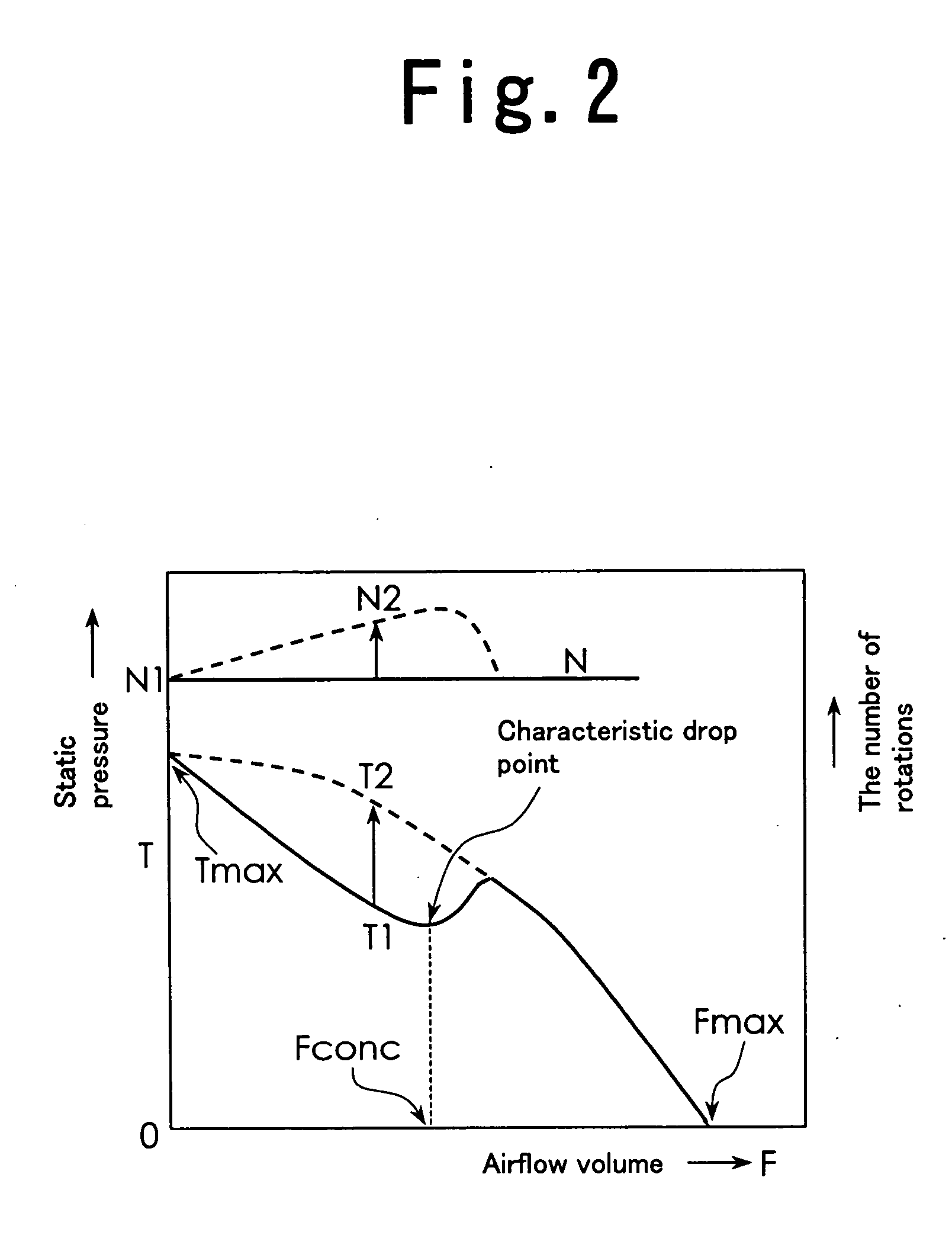
[0011] Furthermore, the mounted microcomputer makes it easier to operate the speed control command for improving the airflow-static pressure characteristic, resulting in obtaining arbitrary airflow-static pressure characteristic.
[0012] In order to reduce power consumption as well as the noise produced when the motor rotates at low speed, the speed control command generating means is so constructed as to set the pulse width modulation control frequency of the drive circuit higher when the rotator rotates at low speed than at high speed. Because a vibratory sound of the motor is less loud during rotating at low speed, the pulse width modulation control frequency may be set to 16 KHz or more so that switching sounds get out of the audio frequency range in order to result in decreasing the noise of the fan motor. With this arrangement, the noise produced can be reduced, and an input current value is decreased, resulting in decreasing the power consumption consumed by switching elements. While rotating at high speed, the fan motor produces a louder hissing sound, which is heard when the fan rotates in the air. Since the switching sounds from the switching elements do not become hash, even though the pulse width modulation control frequency is set down to within the audio frequency range, the pulse width modulation control frequency at high speed rotation of the motor may be set to around 1 KHz. A switching loss by the switching elements can be suppressed low by lowering the frequency, though the input current increases, resulting in the reduced power consumption. Therefore, the power consumption at both low and high speed rotations of the motor, as well as the noise at low speed, can be decreased. More specifically, the speed control command generating means may be so constructed that the pulse width modulation control frequency is switched to 16 KHz when the motor rotates at low speed and to 1 KHz when the motor rotates at high speed.

Problems solved by technology

Then the conventional brushless fan motor has had a problem that a circuitry configuration in the brushless direct current fan motor was complicated, because an additional circuit was needed to convert a digital command from the external equipment into an analog voltage signal for processing.

Method used


Image

  • Brushless dc fan motor
  • Brushless dc fan motor
  • Brushless dc fan motor

Examples


Embodiment Construction

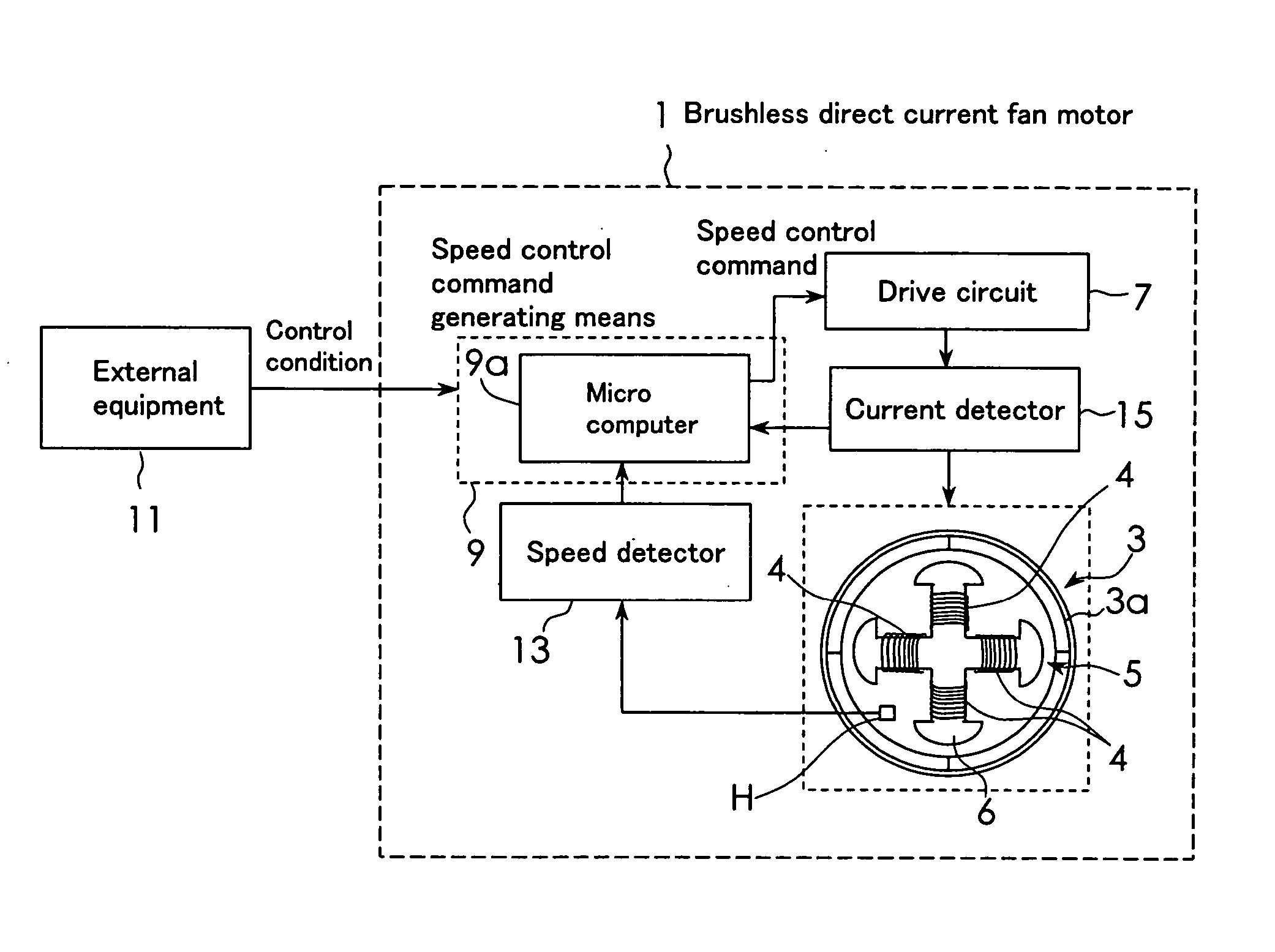
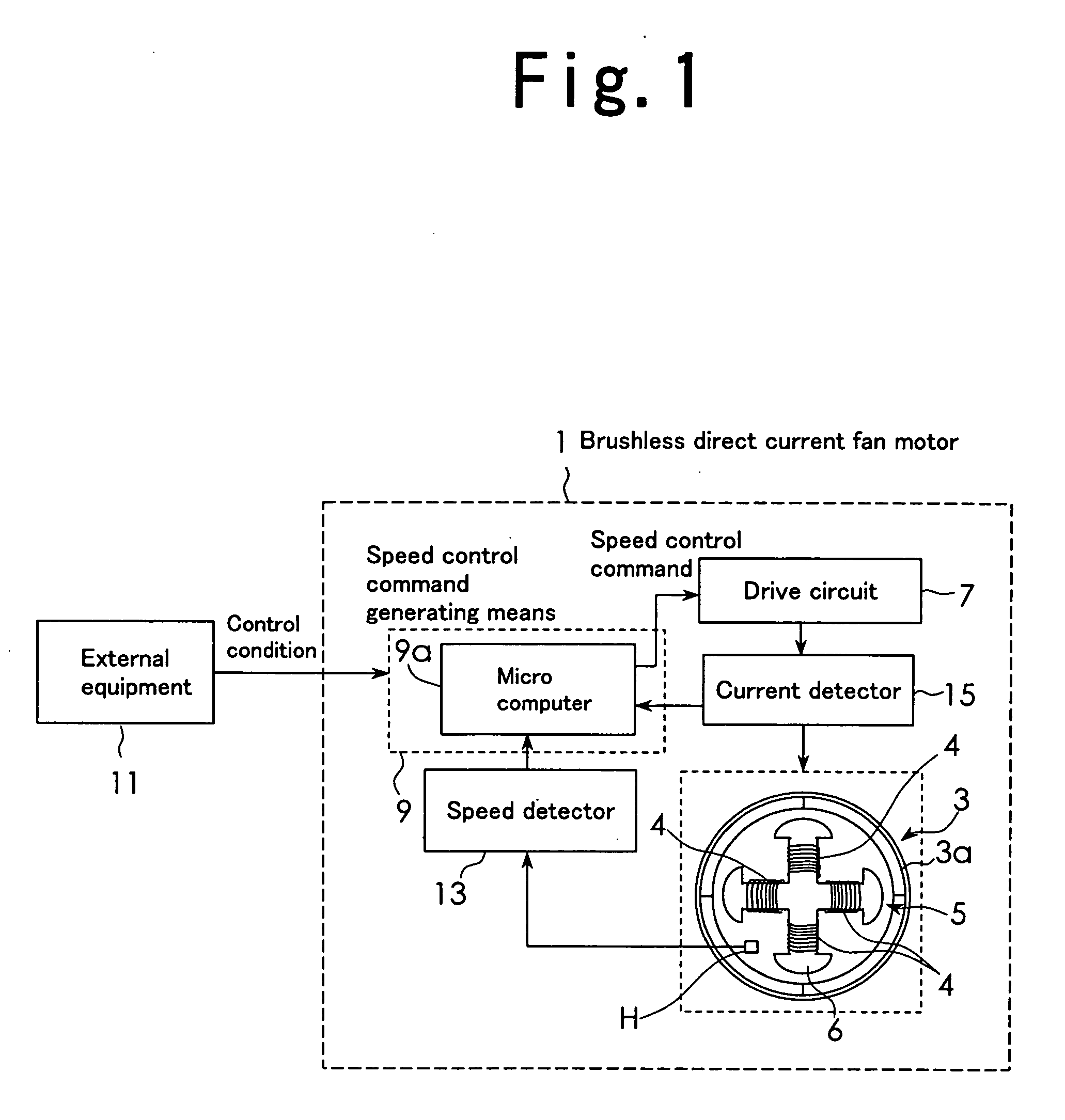
[0017] An embodiment of the present invention will be described in detail with reference to the accompanying drawings. FIG. 1 is a block diagram illustrating an example of a construction of a brushless direct current fan motor according to an embodiment of the present invention. In FIG. 1, a brushless direct current fan motor 1 comprises a rotor 3 having a plurality of blades, not shown, mounted at an outer peripheral portion of a magnetic rotor 3a, and a stator 5 in which a plurality of excitation windings 4 to be excited to rotate the rotor 3 are wound around a core 6. A hole effect element H is provided at the stator 5 side in order to detect a location of the magnetic rotor.

[0018] A drive circuit 7 includes a plurality of switching elements for supplying excitation current to the excitation wirings 4, and a pulse width modulation control signal generating means for PWM controlling the plurality of switching elements. A circuit substrate with the drive circuit 7 mounted thereon ...


PUM


Abstract

A brushless DC fan motor capable of communicating with an external apparatus while simplifying the circuitry. A speed control command generator, which generates a command for controlling the rotational speed of the rotor, include a microcomputer (9a) capable of bi-directional communication with an external apparatus (1) by serial communication based on a predetermined communication protocol. The microcomputer (9a) operates the speed control command based on control conditions transmitted from the external apparatus (1) and a signal indicative of the rotational speed and / or the exciting current detected by a speed detector (13) and / or a current detector (15) incorporated in the brushless DC fan motor (1). A drive circuit (7) controls the exciting current by PWM control according to an optimal speed control command.

Description

FIELD OF THE INVENTION [0001] The present invention relates to a brushless direct current fan motor. BACKGROUND OF THE INVENTION [0002] The brushless direct current fan motor comprises a rotor having a plurality of blades, a stator having excitation windings to be excited to rotate the rotor, a drive circuit, arranged at the stator side, for supplying excitation current to the excitation windings according to a speed control command, and a speed control command generating means, arranged at the stator side, for executing operation according to an inputted signal and generating the speed control command. The excitation current is switched corresponding to the location of the rotor detected by a location detector including a hole effect element. In many cases, all of the input signals to be inputted to the speed control command generating means are internally generated in the fan motor. In some cases, however, the inputted signals are input from an external circuit or external equipme...

Claims


Application Information

Patent Timeline
Patent Type & Authority Applications(United States)
IPC IPC(8): F04D27/02F04D27/00H02P6/06H02P6/08H02P6/17H02P7/08
CPCF04D27/004Y02B30/70
Inventor MURARA, MASATOKUDOU, NARUHIKOTAKAKUWA, MUNENORI
Owner SANYO DENKI CO LTD
Learn More