
Global Automatic RC Time Constant Tuning Circuit and Method for on Chip RC Filters

Inactive Publication Date: 2005-11-17
VIA TECH INC
View PDF6 Cites 27 Cited by
  • Summary
  • Abstract
  • Description
  • Claims
  • Application Information

AI Technical Summary

Benefits of technology

[0013] It is an advantage of the claimed invention that only one time of measurement of the RC time constant of the tuning circuit is needed for tuning the RC time constant of the RC filter. In the claimed invention, there is no need to duplicate the resistors and capacitors of the filter. Hence the area of IC is reduced as well.

Problems solved by technology

Hence RC filters are more controllable and broadly adopted, however, there are still variances in RC filter designs.
Therefore, the actual value of the RC time constant is not always identical to the design value of the RC time constant, and the accuracy of the filter and the performance of filtering are consequently affected.
In consequence, the performance of the RC filter shifts over a dramatic range, which is very unfavorable to circuits that need a precise frequency response.
Though this tuning circuit does not utilize external resistors and capacitors, power consumption is increased due to the utilization of active resistors.
Also, the MOSFETs make such designs more difficult to implement in a low voltage potential environment.
Furthermore, the resistors and the array of capacitors of the RC filter that need to be duplicated in order to form the reference RC network, occupy a huge area of IC.
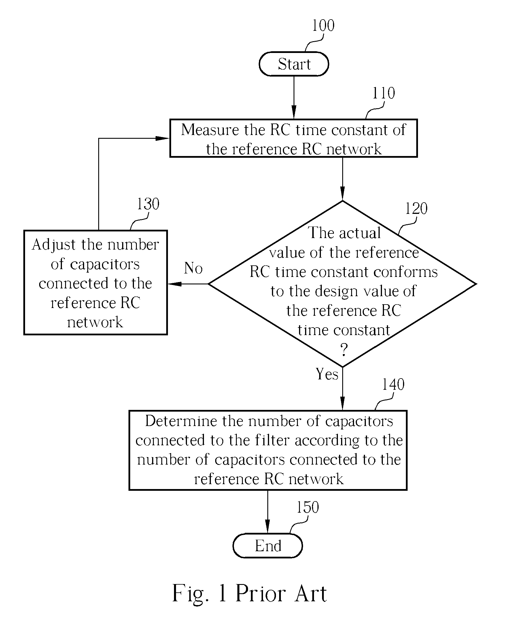
However, no matter what algorithm is utilized, it still takes a relatively long time to identify the most appropriate number of capacitors to be connected to the reference RC network for making the actual RC time constant equal to the design value.
Naturally, this problem will be compounded if the circuit comprises more than one filter.

Method used


Image

  • Global Automatic RC Time Constant Tuning Circuit and Method for on Chip RC Filters
  • Global Automatic RC Time Constant Tuning Circuit and Method for on Chip RC Filters
  • Global Automatic RC Time Constant Tuning Circuit and Method for on Chip RC Filters

Examples


Embodiment Construction

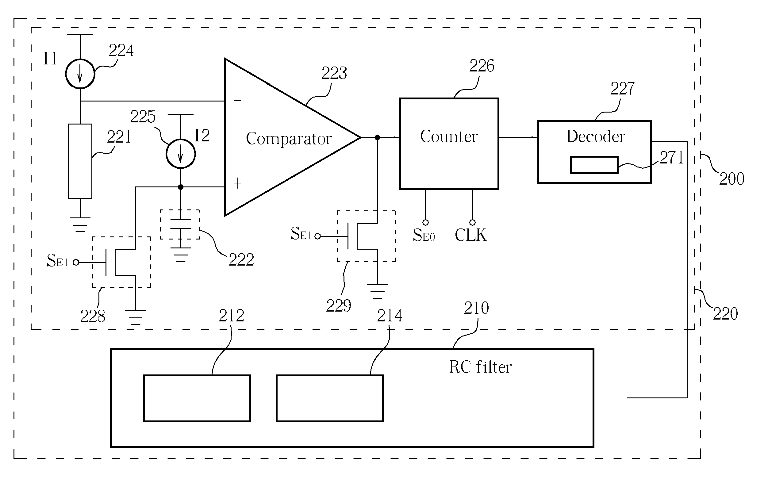
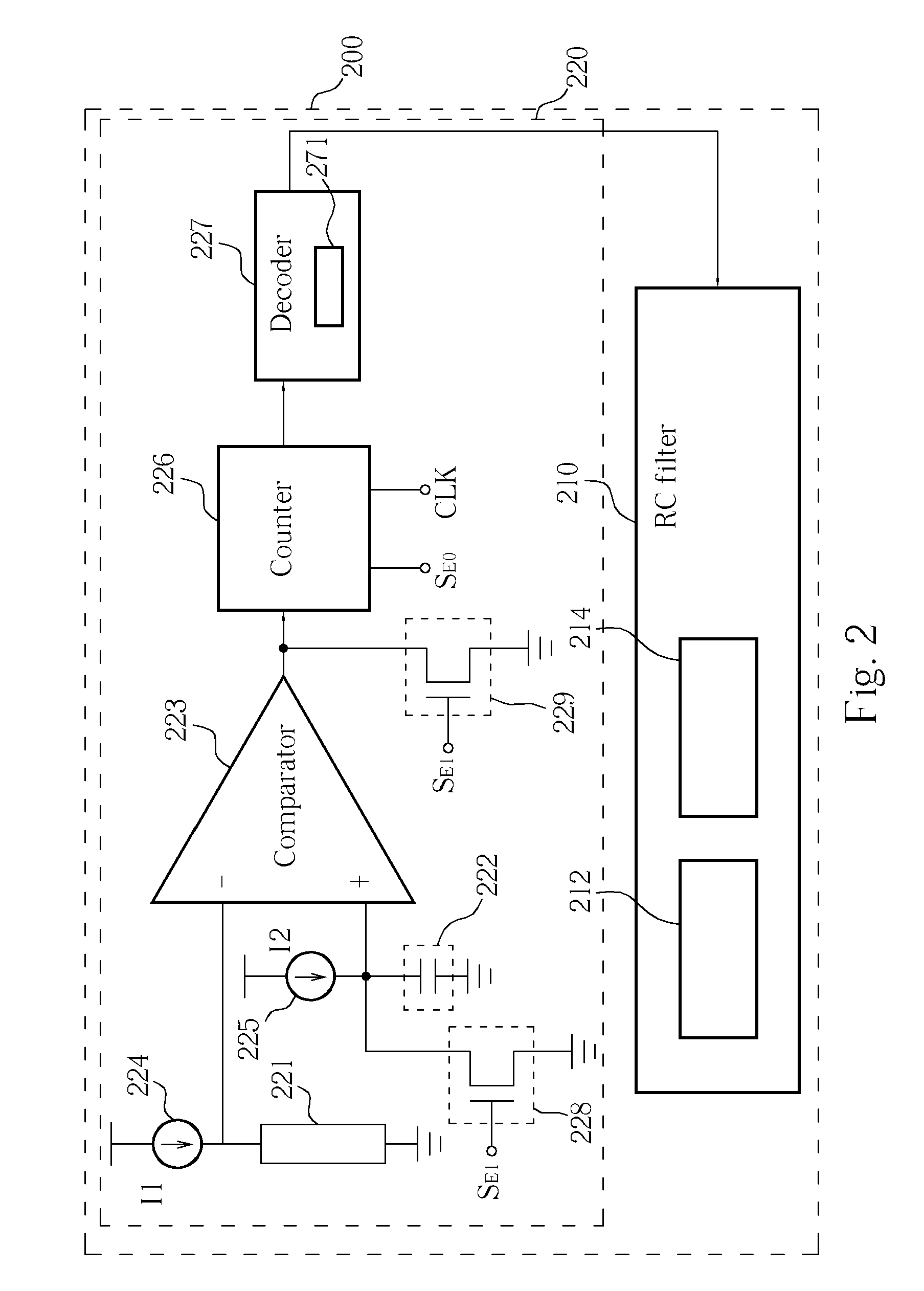
[0020] Please refer to FIG. 2. FIG. 2 is a block diagram of the present invention semiconductor device 200. The semiconductor device 200 comprises an RC filter 210 and a tuning circuit 220. The RC filter 210 includes a resistor network 212 comprising a plurality of resistors and a capacitor network 214 comprising a plurality of capacitors. The tuning circuit 220 is responsible for controlling the numbers of adopted resistors and adopted capacitors for tuning the RC time constant of the RC filter 210. The tuning circuit 220 includes a reference resistor 221, a reference capacitor 222, a first current source 224, a second current source 225, a comparator 223, a counter 226 and a decoder 227. The material of the reference resistor 221 is the same as the material of the resistors of the resistor network 212, and the material of the reference capacitor 222 is the same as the material of the capacitors of the capacitor network 214. The current provided by the first current source 224 is 1...


PUM


Abstract

A method for RC time constant tuning includes biasing a reference resistor and charging a reference capacitor, transmitting a start signal to a counter when beginning charging, inputting the results of biasing and charging to a comparator for comparing, and sending a stop signal to the counter when the result of the comparison conforms to a predetermined rule, counting a number of clock cycles received by the counter from the time of receiving the start signal to the time of receiving the stop signal, and deciding a number of resistors or a number of capacitors utilized by an RC filter according to the number of the clock cycles received by the counter.

Description

BACKGROUND OF INVENTION [0001] 1. Field of the Invention [0002] The present invention relates to an RC time constant tuning circuit and a related method, and more particularly, to an RC time constant tuning circuit and a related method that decides a number of resistors or a number of capacitors utilized by an RC filter according to the number of the clock cycles received by the counter. [0003] 2. Description of the Prior Art [0004] Filters are utilized commonly in many fields of communication. As is widely known, the variance of resistor-capacitor filters (RC filters) is smaller than that of gmC filters. Hence RC filters are more controllable and broadly adopted, however, there are still variances in RC filter designs. Therefore, the actual value of the RC time constant is not always identical to the design value of the RC time constant, and the accuracy of the filter and the performance of filtering are consequently affected. Without calibration, the difference between the actual ...

Claims


Application Information

Patent Timeline
IPC IPC(8): H03B1/00H03H5/00H03H7/32
CPCH03H7/325
Inventor LIN, JOANNA
Owner VIA TECH INC
Learn More