
Adjustable height access device for treating the spine of a patient

a height access device and patient technology, applied in the field of adjustable height access devices for treating the spine of patients, can solve the problems of insufficient narrow cannula for performing one-level spinal fixation procedures, high scarring risk of traditional surgical procedures of this type, and extended recovery tim

Active Publication Date: 2005-11-03
ZIMMER BIOMET SPINE INC
View PDF85 Cites 78 Cited by
  • Summary
  • Abstract
  • Description
  • Claims
  • Application Information

AI Technical Summary

Benefits of technology

"The patent text describes a device and method for providing minimally invasive access to the spine for various procedures. The device includes an elongate body with a longitudinal axis and an inner surface that defines a passage through which surgical instruments can be inserted. The device can be adjusted to have a greater cross-sectional area of the passage at a first location than at a second location, allowing for a variety of procedures to be performed via a single access device. The method involves inserting the elongate body through an incision in the skin of the patient and adjusting the height between the skin and the proximal end of the elongate body to facilitate access to the surgical location. Overall, the device and method provide a minimally invasive solution for spine procedures."

Problems solved by technology

Spinal surgery presents significant difficulties to the physician attempting to reduce chronic back pain or correct spinal deformities without introducing additional trauma due to the surgical procedure itself.
Consequently, traditional surgical procedures of this type carry high risks of scarring, pain, significant blood loss, and extended recovery times.
A narrow cannula is typically insufficient to perform one level spinal fixation procedures, which requires visualization of two vertebrae and introduction of screws, rods, as well as other large spinal fixation devices.

Method used


Image

  • Adjustable height access device for treating the spine of a patient
  • Adjustable height access device for treating the spine of a patient
  • Adjustable height access device for treating the spine of a patient

Examples


Embodiment Construction

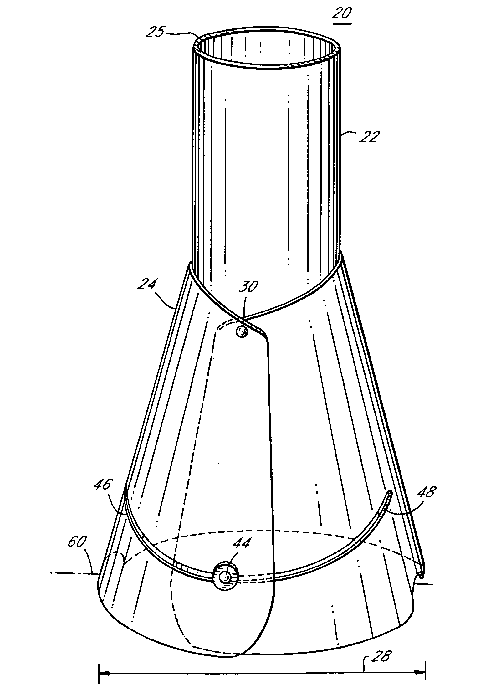
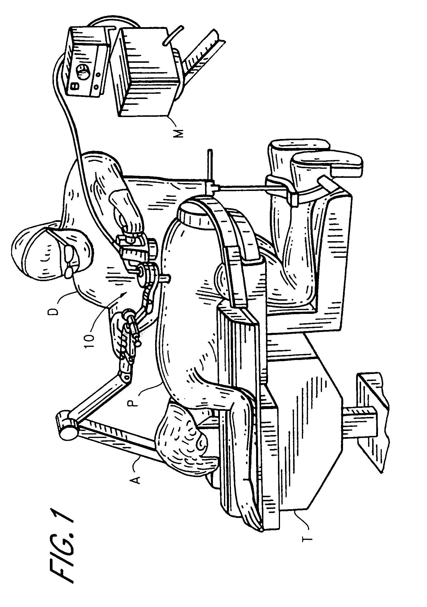
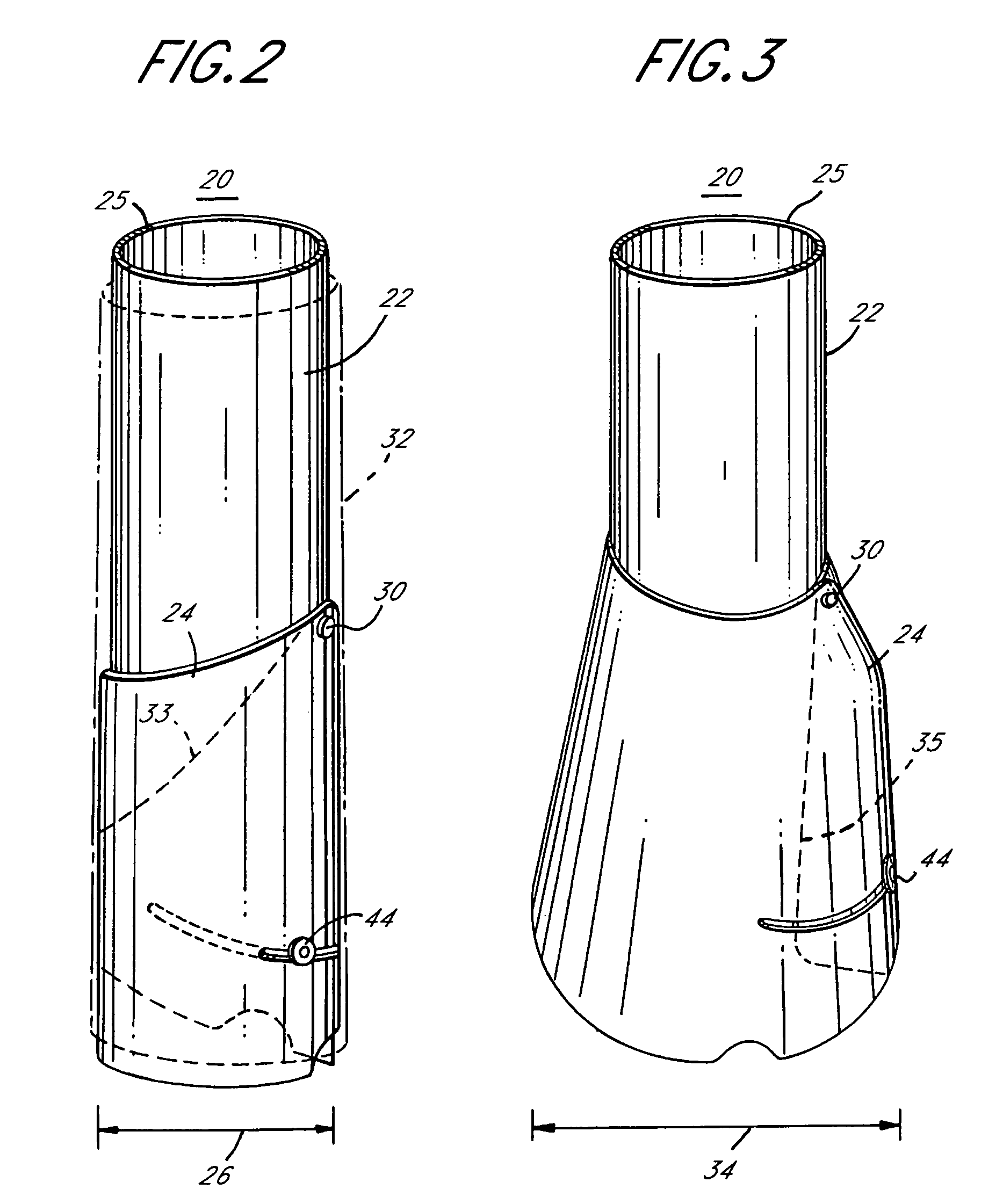
[0304] As should be understood in view of the following detailed description, this application is primarily directed to, though not necessarily limited to, apparatuses and methods for treating the spine of a patient through an access device. More particularly, the systems described below provide access to surgical locations at or near the spine and provide a variety of tools useful in performing treatment of the spine. Some embodiments, discussed below in Section III(B), include an access device that is capable of being adjusted along a longitudinal axis thereof. In some embodiments, such adjustment enables the height (e.g., the dimension of the device from the skin to a proximal end thereof) to be adjusted. An adjustable height access device advantageously allows a surgeon to adjust the height of the access device based upon the anatomy of the patient and the type of procedure to be performed. Also, the systems described herein enable a surgeon to perform a wide variety of methods ...


PUM


Abstract

A device for providing access to a surgical location within a patient is provided. The device includes an elongate body and a sleeve. The elongate body has an outer surface, an inner surface, and a distal portion. The inner surface defines a passage that extends through the elongate body along a longitudinal axis through which surgical instruments can be inserted to the surgical location. The distal portion is capable of having an expanded configuration when inserted within the patient. In the expanded configuration, the cross-sectional area of the passage at a first location is greater than the cross-sectional area of the passage at a second location, wherein the first location is distal to the second location. The sleeve is configured to be moved relative to the elongate body along the longitudinal axis to increase or to decrease the length of the passage along the longitudinal axis.

Description

PRIORITY INFORMATION [0001] This application is based on and claims priority to U.S. Provisional Patent Applications No. 60 / 514,559 (filed Oct. 24, 2003), 60 / 545,587 (filed Feb. 18, 2004), and 60 / 579,643 (filed Jun. 15, 2004). This application also is a continuation-in-part of U.S. patent application Ser. No. 10 / 927,633 (filed Aug. 26, 2004), and is a continuation-in-part of U.S. patent application Ser. No. 10 / 926,579 (filed Aug. 26, 2004). The entire contents of each of the foregoing applications is hereby expressly incorporated by reference herein.BACKGROUND OF THE INVENTION [0002] 1. Field of the Invention [0003] This application relates to surgical systems and assemblies that include an access device for minimally invasive surgery, and in particular relates to systems and devices that provide access to a surgical location, e.g. adjacent a spine, for one or more instruments to perform a procedure at the surgical location. [0004] 2. Description of the Related Art [0005] Spinal sur...

Claims


Application Information

Patent Timeline
Patent Type & Authority Applications(United States)
IPC IPC(8): A61B1/31A61B1/313A61B17/00A61B17/02A61B17/17A61B17/32A61B17/34A61B17/70A61B17/88A61B19/00A61M1/00A61M29/00
CPCA61B17/3439A61B17/3423A61B17/7001A61B17/7007A61B17/701A61B17/7032A61B17/7037A61B17/7038A61B17/7041A61B17/7044A61B17/7058A61B17/7082A61B17/7083A61B17/7085A61B17/8875A61B19/22A61B19/26A61B19/5202A61B19/5212A61B2017/00261A61B2017/00557A61B2019/462A61B2019/481A61B2019/5206A61B2217/005A61B2217/007A61B1/00149A61B1/00154A61B1/31A61B1/313A61B1/3135A61B17/00A61B17/02A61B17/0218A61B17/1757A61B17/32002A61B17/3403A61B17/3462A61B34/70A61B90/30A61B90/361A61B90/50A61B2090/062A61B2090/08021A61B2090/306A61B90/11
Inventor DIPOTO, GENE P.
Owner ZIMMER BIOMET SPINE INC
Learn More