
Apparatus and methods for securing tissue to bone

a technology of tissue and bone, applied in the field of surgical arthroscopy, can solve the problems of difficulty in securing tissue to bone, etc., and achieves the effect of convenient us

Inactive Publication Date: 2005-11-03
C2M MEDICAL INC
View PDF96 Cites 274 Cited by
  • Summary
  • Abstract
  • Description
  • Claims
  • Application Information

AI Technical Summary

Benefits of technology

[0022] In view of the foregoing, it is an object of the present invention to provide apparatus and methods for securing tissue to bone that are easy to use and do not require a large incision.
[0023] It is also an object of the present invention to provide apparatus and methods for securing tissue to bone that allow a surgeon direct tactile feedback of the tension in the suture between the tissue and the bone.
[0024] It is a further object of the present invention to provide apparatus and methods for securing tissue to bone that allow a surgeon to tension both ends of a suture individually to fine-tune the placement of the tissue with respect to the bone.

Problems solved by technology

There are various drawbacks associated with such previously-known suture anchoring systems.
However, when performing the procedure under arthroscopic visualization and having minimal clearance, it is often difficult for the surgeon to perform the maneuvers necessary to tie a knot in the confined working space.
Further, previously-known suture anchoring systems generally do not allow the surgeon direct tactile feedback of the tension in the suture between the tissue and the bone.
For example, in those systems where only one free end of the suture may be manipulated by a physician, difficulties may arise in approximating the position of the tissue with respect to the bone.
However, such systems have various drawbacks, including not being able to manually determine the tension of the tissue, and also risking the possibility that the knot will become embedded within the tissue.
First, the device appears to rely on tension alone to secure the tissue to the bone.
Accordingly, it is possible that incidental tensile forces applied to the free suture end may unexpectedly unlock the device.
In short, when tensioning the free end of the suture is the means for locking and unlocking the device, it may be difficult to lock the device in a desired position, or the device may come unlocked at an undesirable time.
Another drawback of the device described in the Foerster patent is that one of the suture ends is “bound” to the tissue.
The device described in the West patent does not appear to permit suture adjustments after the suture is locked in place.
Therefore, it is not possible to adjust the suture further because it would be necessary to distally advance the shaft to do so, i.e., to remove the compressive force imposed upon the suture.
However, the shaft cannot be advanced distally because the expandable members, secured within the bone, would prohibit such movement.

Method used


Image

  • Apparatus and methods for securing tissue to bone
  • Apparatus and methods for securing tissue to bone
  • Apparatus and methods for securing tissue to bone

Examples


Embodiment Construction

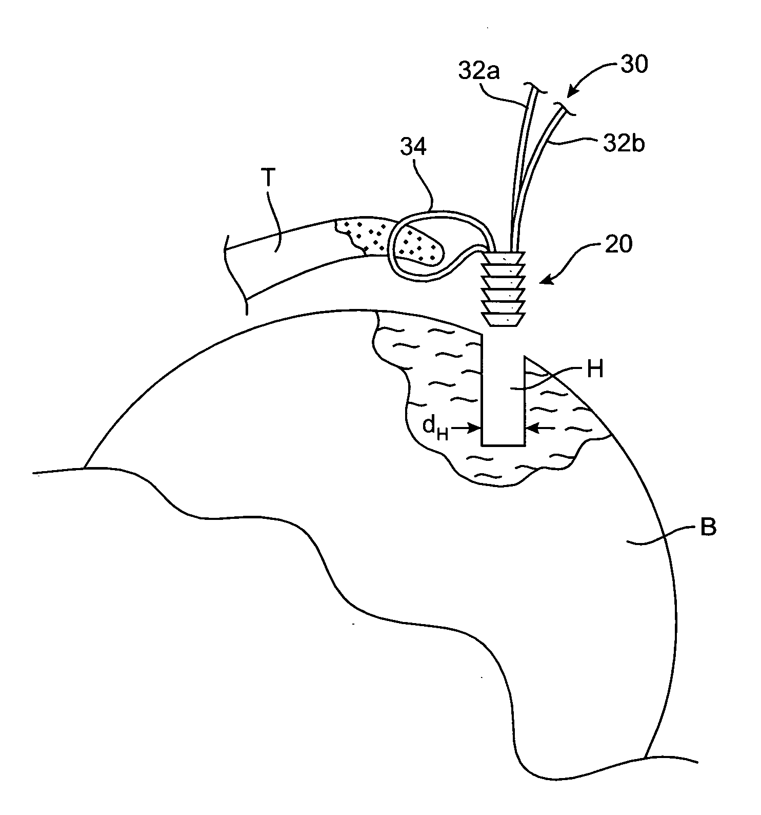
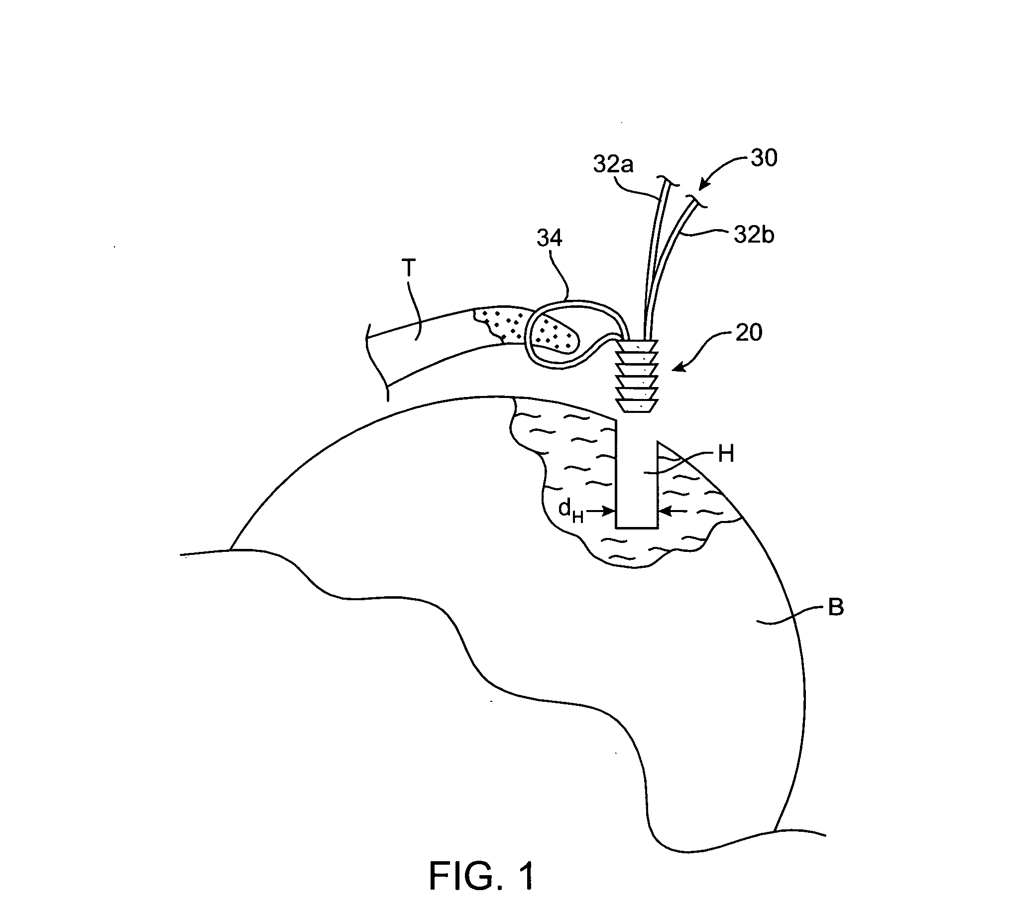
[0058] Referring now to FIG. 1, a schematic of a bone and tissue interface is shown primarily for illustrative purposes. In FIG. 1, tissue T has a torn end and it is desirable to secure the torn end to a section of bone B. In a first step, hole H having diameter dH is drilled in bone B, as depicted, using techniques that are well known in the art.

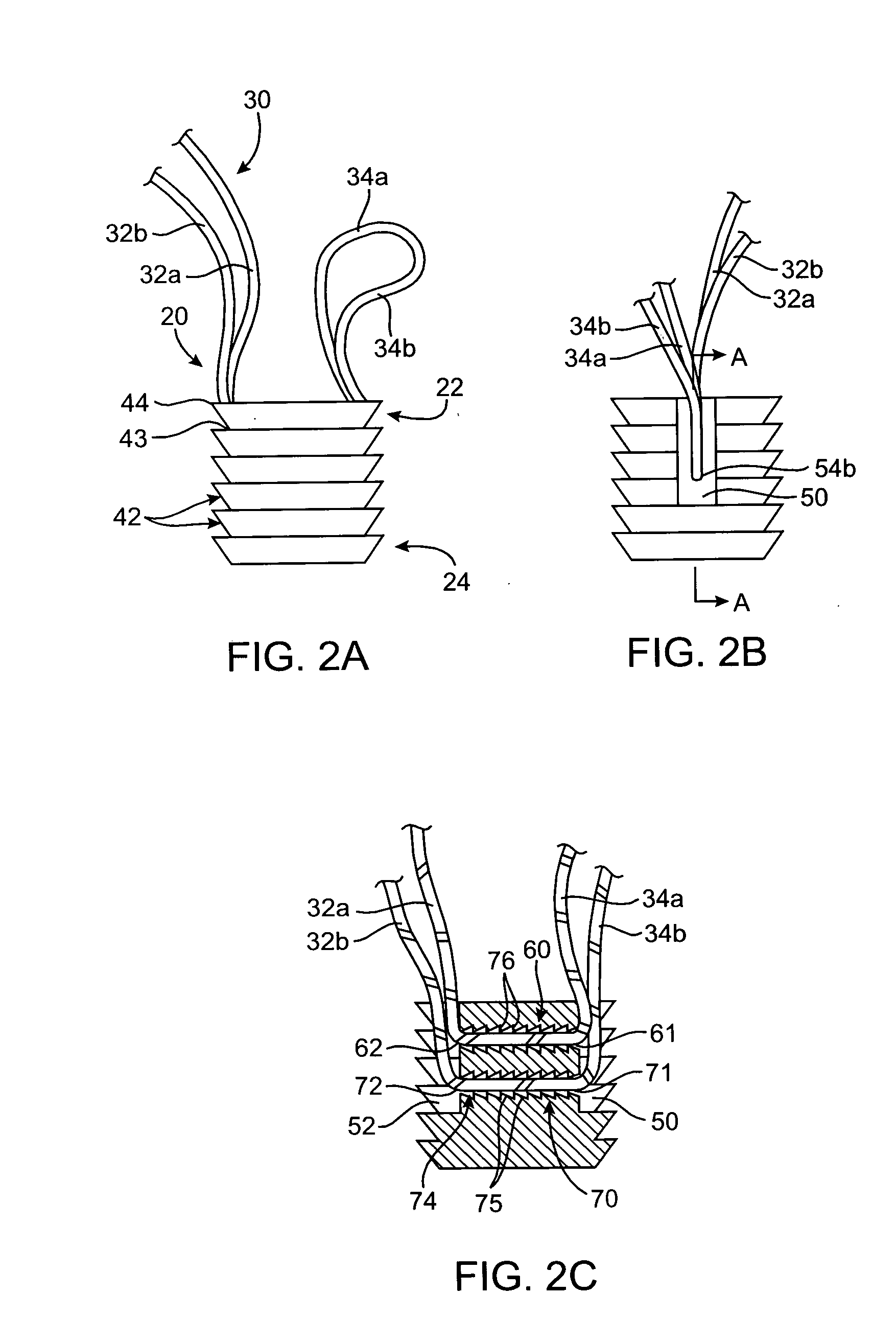
[0059] Bone anchor member 20, which will be described in greater detail in FIGS. 2A-2C hereinbelow, is shown as a means for securing tissue T to bone B. Bone anchor member 20 is configured to be used in conjunction with a suture length 30. Suture 30 has first and second ends 32a and 32b, which are coupled to bone anchor member 20, as described in FIGS. 2A-2C hereinbelow. It should be noted that a central region of suture 30 forms loop 34, which is threaded through a section of tissue T near the torn end of the tissue, as depicted in FIG. 1, using techniques that are known in the art.

[0060] Referring now to FIGS. 2A-2C, features of bone an...


PUM


Abstract

The present invention relates to apparatus and methods for securing tissue to bone using a suture anchoring system that provides enhanced tactile feedback and does not require tying a suture knot. In each embodiment, a surgeon can individually tension the free ends of the suture to fine-tune the placement of the tissue with respect to the bone, and then secure the suture without tying a knot. In several embodiments of the present invention, the device may be transformed between locked and unlocked suture states, thereby allowing further fine-tuning of the tension in the suture.

Description

FIELD OF THE INVENTION [0001] The present invention relates to the field of surgical arthroscopy, and more particularly, to apparatus and methods for facilitating the attachment of tissue to bone using a suture anchoring system that provides enhanced tactile feedback and does not require tying a suture knot. BACKGROUND OF THE INVENTION [0002] Many attempts have been made to provide devices that allow the arthroscopic securing of torn tissue to a substrate bone. For example, there have been numerous devices designed for the shoulder to allow a torn rotator cuff to be secured to the humeral head. [0003] Typically, in a first step, a hole is drilled into the bone under arthroscopic visualization. A length of a suture generally is employed to permit securing of the tissue to the bone. The suture length is threaded through a portion of the tissue, and also is coupled to a bone anchor configured to be inserted into the hole in the bone. One or both of the suture ends may extend outside of...

Claims


Application Information

Patent Timeline
Patent Type & Authority Applications(United States)
IPC IPC(8): A61B17/04A61B17/58
CPCA61B17/0401A61B2017/0414A61B2017/0445A61B2017/0459A61B2017/0453A61B2017/0456A61B2017/0458A61B2017/045
Inventor FANTON, GARY S.ASHLEY, JOHN E.
Owner C2M MEDICAL INC
Learn More