
Crystallization method and crystallization apparatus

a crystallization apparatus and crystallization method technology, applied in the direction of photomechanical apparatus, polycrystalline material growth, instruments, etc., can solve the problems of inability to exhaust all gas, inability to completely remove impurities and air bubbles that mix into grown single crystals, and greatly deteriorated optical performan

Inactive Publication Date: 2005-11-03
CANON KK
View PDF20 Cites 6 Cited by
  • Summary
  • Abstract
  • Description
  • Claims
  • Application Information

AI Technical Summary

Benefits of technology

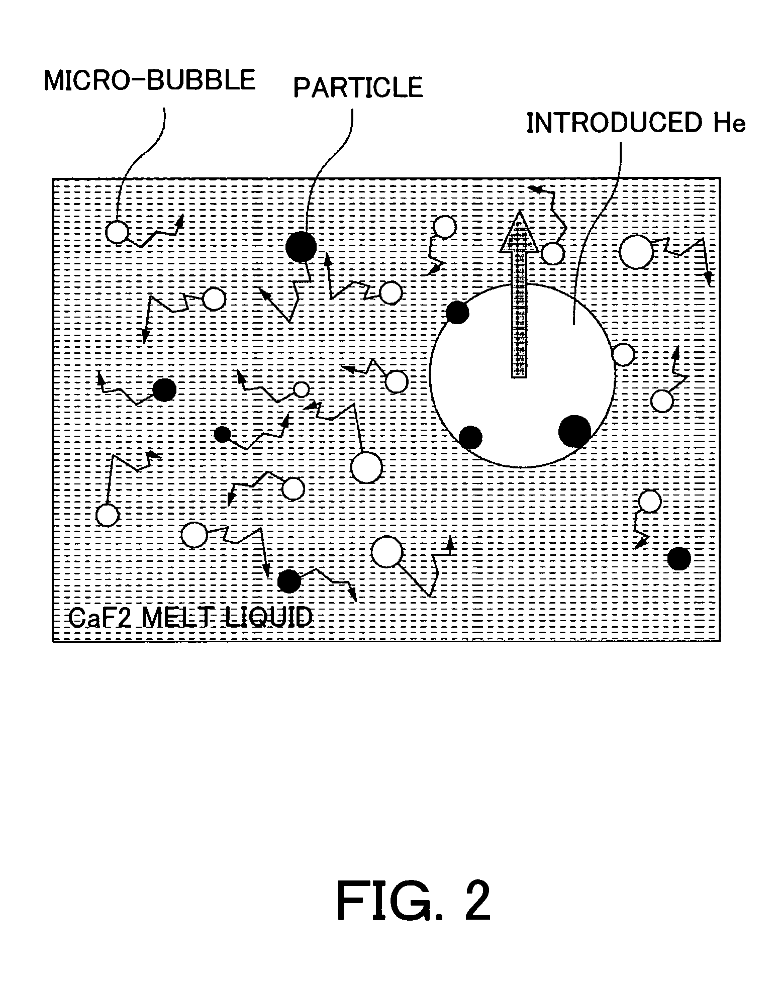
[0014] The present invention can produce a crystal with low concentration of impurities and does not include air bubbles etc. by introducing a gas into a melt liquid used for the crystal growth and shaking.

Problems solved by technology

More particularly, when calcium fluoride is used as an optical element for ultraviolet etc. with short wavelength, an optical performance is greatly deteriorated because of extremely small amount of impurities, so a scavenger to remove impurities is added to the melt liquid during the crystal growth process, and high-purity single crystal is manufactured.
However, in actual crystal growth process, impurities and air bubbles that mix into the grown single crystal cannot always be completely removed.
However, all the gas cannot be exhausted, and remains in the grown crystal for the above reasons.

Method used


Image

  • Crystallization method and crystallization apparatus
  • Crystallization method and crystallization apparatus
  • Crystallization method and crystallization apparatus

Examples


first embodiment

[0034] The instant embodiment explains an example of manufacturing the calcium fluoride chiefly used for an optical material by the above crystallization method.

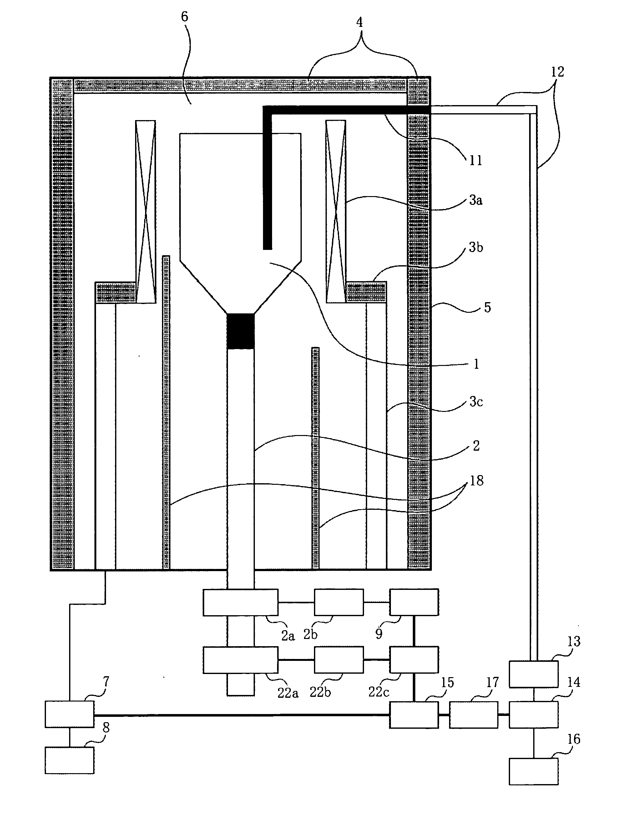
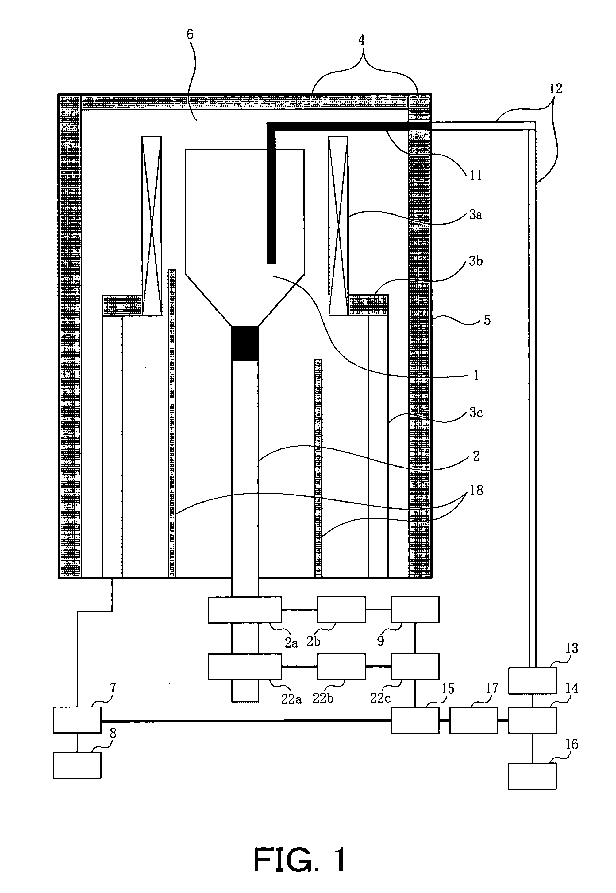
[0035] A material that adds ZnF2 of 0.1% by weight as the scavenger to high-purity calcium fluoride polycrystal which is a material of calcium fluoride single crystal is placed into the carbon crucible 1 shown in FIG. 1. After the chamber 6 is vacuum-exhausted, the side heater 3 is electrified to heat the chamber 6, the crucible 1 is adjusted to about 1360° C., and the material in the crucible 1 is melted. The melt state is maintained for about three hours for the oxygen removal reaction to occur in the melt liquid by the scavenger, and then, the gas introducing port 11 made of carbon is inserted in the crucible 1, and the state is maintained for seven hours while introducing the helium gas with 300 sccm. Meanwhile, the chamber 6 is maintained to the pressure of 1 Torr or less to easily deaerate the introduced helium gas.

[...

second embodiment

[0067]FIG. 8 is a typical sectional view of a second crystallization apparatus according to the present invention. FIG. 8 shows a structure when this invention is executed with the crystallization apparatus by Czochralski method. In the instant embodiment, a description will be given of manufacturing of lithium tantalate (LiTaO3) (hereafter, LT) crystal as one example of the grown crystal.

[0068] In FIG. 8, a crucible 1a that houses a melting material as a crystalloid is installed in the housing 5 that form the chamber 6. An insulator 4 is installed inside the housing 5, and protects the housing 5 from the high-temperature. The chamber 6 is vacuum exhausted to the pressure of 1E-4 or less (Torr) by the exhaust apparatus (not shown).

[0069] A RF (radiofrequency generation) coil 21 that heats the material in the crucible 1a is arranged outside of the chamber 6. The RF coil 21 is supplied an electric power from a radiofrequency generation power source 20 that is controlled by a power s...


PUM

PropertyMeasurementUnit
pressureaaaaaaaaaa
diameteraaaaaaaaaa
melting pointaaaaaaaaaa

Abstract

A crystallization method includes the steps of melting a crystallized material in a crucible by heating, and growing a crystal by cooling and coagulating the melted material, wherein said melting step includes introducing a predetermined gas into the melted material.

Description

BACKGROUND OF THE INVENTION [0001] The present invention relates mainly to a method and apparatus that grows a crystal by a solidification process that solidifies melted crystal material. [0002] Various existing methods to produce an excellent single crystal by controlling a solidification process that solidifies melted crystal material are conventional used for manufacture various crystal materials. [0003] Typical manufacturing method for the single crystal is the CZ (Czochralski) method that slowly lifts a solid crystal from solidifying melted material in a crucible and the Bridgman method that is solidifies the melted material in one direction by changing a temperature distribution in the crucible that houses the melted material. The choice of single crystal manufacturing method depends on required characteristics and performance from the manufactured single crystal. [0004] The single crystal manufactured by the above crystallization method is, generally, high-purity. Moreover, i...

Claims


Application Information

Patent Timeline
Patent Type & Authority Applications(United States)
IPC IPC(8): C30B11/00G02B1/02C30B11/04C30B21/02C30B29/12C30B29/30G03F7/20
CPCC30B11/00C30B29/12G02B1/02Y10T117/102Y10T117/10Y10T117/1008G03F7/70958
Inventor OYAMA, YASUNAOTERASHIIMA, KAZUTAKA
Owner CANON KK
Learn More