
Mid-kiln injection of waste-derived materials

Inactive Publication Date: 2005-11-03
LONE STAR INDS
View PDF14 Cites 3 Cited by
  • Summary
  • Abstract
  • Description
  • Claims
  • Application Information

AI Technical Summary

Benefits of technology

[0011] In order to address these needs, the present invention contemplates modifications to a process for the production of cement clinker in a heated rotary kiln. In particular, the invention contemplates the introduction of non-traditional materials into the kiln as the clinker is being produced. In one embodiment, weathered clinker is injected into the kiln prior to the discharge end of the kiln. The water content of the weathered clinker is driven off by the heat of the kiln and the weathered clinker admixes with the new clinker as it is produced. The weathered clinker thus augments the clinker production of the kiln without the need for additional raw mix.
[0014] It is one object to provide improvements to the process for production of cement clinker. One of the improvements is to increase the clinker yield or output without the necessity of increasing the amount of raw mix fed to the kiln. Another object is to allow for the production of additional clinker where the system to introduce raw mix feed is used to maximum capacity, but the kiln has capacity to produce additional clinker. That object may be accomplished through introduction of weather clinker outside the raw mix feed system (i.e., though mid-kiln introduction). A further improvement reduces certain noxious emissions in the flue gases generated during the clinker production process.
[0015] A further object is to reduce the disposal and environmental impact of certain materials that are otherwise problematic. This object can be achieved with materials that can augment the clinker production process, either as a supplemental fuel, as a “filler” material, or as a pollution reducing material.

Problems solved by technology

These non-traditional materials can pose disposal and environmental problems, so their use as supplemental fuel in the production of cement clinker solves two problems—the disposal of the non-traditional materials and the reduction of fuel requirements for the kiln.

Method used


Image

  • Mid-kiln injection of waste-derived materials
  • Mid-kiln injection of waste-derived materials
  • Mid-kiln injection of waste-derived materials

Examples


Embodiment Construction

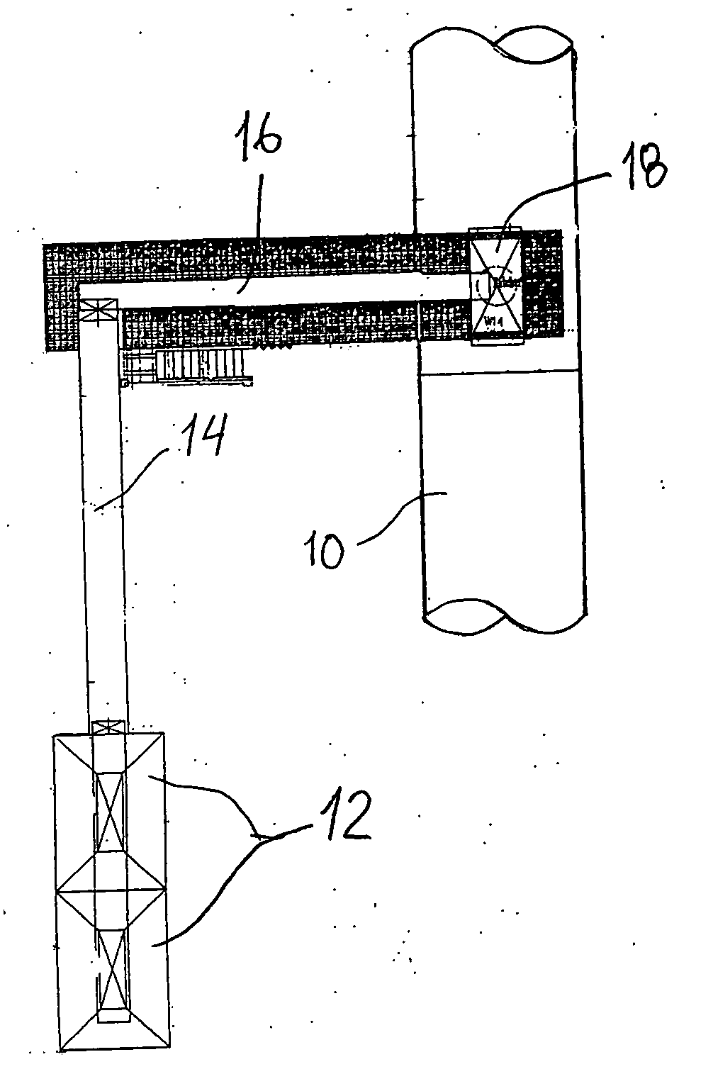
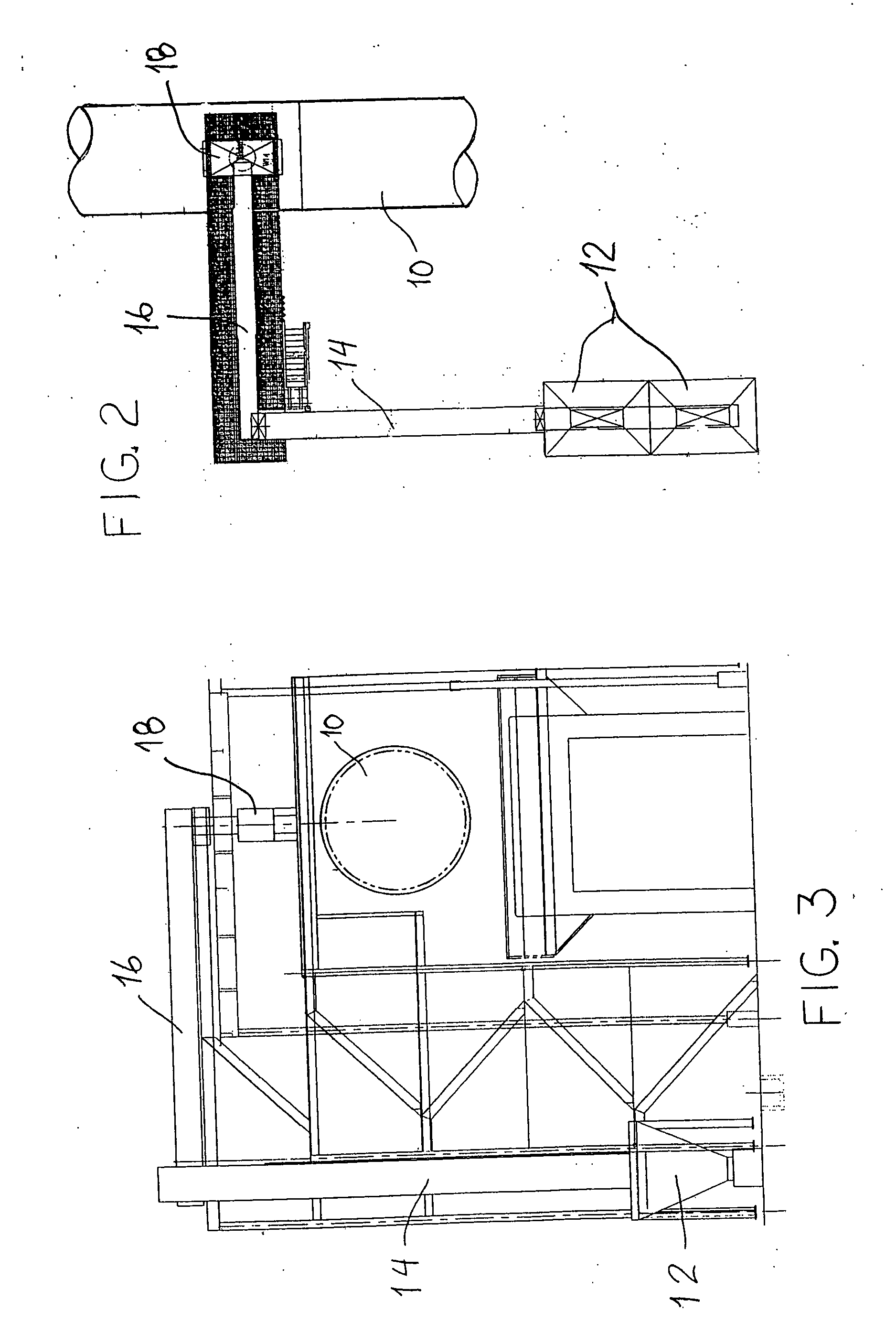
[0021] For the purposes of promoting an understanding of the principles of the invention, reference will now be made to the embodiments illustrated in the drawings and described in the following written specification. It is understood that no limitation to the scope of the invention is thereby intended. It is further understood that the present invention includes any alterations and modifications to the illustrated embodiments and includes further applications of the principles of the invention as would normally occur to one skilled in the art to which this invention pertains.

[0022] The present invention contemplates the addition of non-traditional waste materials to a cement kiln, especially a rotary long kiln. One such waste material is weathered clinker. Weathered clinker is previously manufactured clinker that has been stored for a significant amount of time, usually outdoors. Most cement production is seasonal, with the highest demand for clinker coming in the summer. During t...


PUM


Abstract

A method for the production of cement clinker comprises the introduction of non-traditional materials into the kiln, preferably at a mid-kiln locations. The non-traditional materials are materials that are difficult, expensive or environmentally challenging for disposal. In one embodiment, weathered clinker is introduced into the kiln to admix with the raw material mix to augment clinker production. In another embodiment, bird, animal or human manure is added to the kiln so that gaseous reducing agents can be released by the manure and combine with certain noxious gases generated during the clinker production, to thereby reduce the noxious gas output. In other embodiments, other non-traditional waste-derived fuels are added to the kiln during clinker production, including railroad ties coated with creosote, industrial, commercial and consumer rubber components, such as rubber hoses, unshredded plastics, and organic materials, such as bird and animal meal.

Description

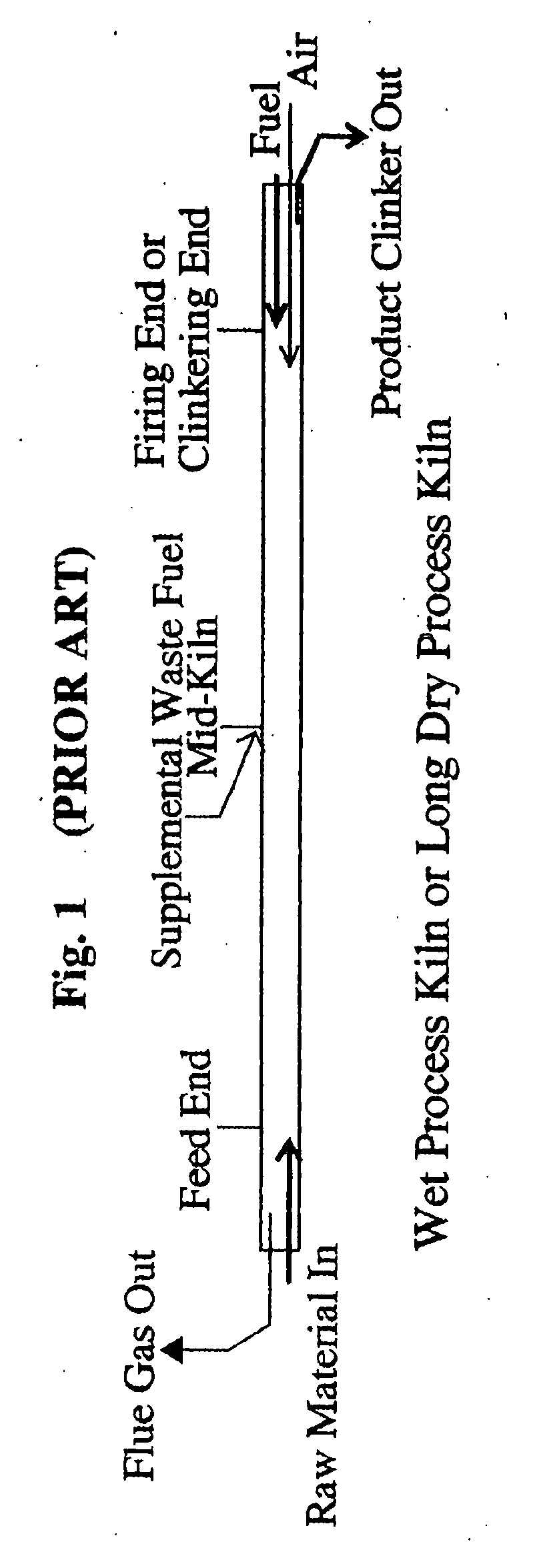
BACKGROUND OF THE INVENTION [0001] This invention relates in general to the manufacture of cement clinker, particularly in rotary kilns. More specifically, the invention relates to the introduction of slag into the kiln to enhance the clinker production process. [0002] The details of a typical cement pyroprocessing operation are well known. For purposes of illustration, one type of rotary kiln for manufacturing Portland cement is depicted in FIG. 1. Air and a primary fuel, such as coal, are injected into the firing or clinkering end of the kiln and are combusted to supply heat energy. Wet or dry raw materials, known as raw mix, for producing cement, such as limestone, clay and sand, are injected into the feed end of the kiln opposite the clinkering end. The kiln is inclined so that as the kiln rotates, the raw materials move through the kiln counter-current to the direction of the flow of the hot combustion gases so that the raw materials are subjected to progressively higher temper...

Claims


Application Information

Patent Timeline
IPC IPC(8): C04B7/24C04B7/36C04B18/18
CPCC04B7/364C04B7/24Y02P40/10
Inventor HOFFIS, LAWRENCE L.
Owner LONE STAR INDS
Learn More