
Fully threaded suture anchor with transverse anchor pin

a transverse anchor and suture technology, applied in the appendix, can solve the problems of suture being exposed to abrasion or cutting, suture attached to the eyelet being vulnerable to abrasion, and the drive head tending to weaken, so as to prevent suture abrasion

Active Publication Date: 2005-10-06
ARTHREX
View PDF12 Cites 277 Cited by
  • Summary
  • Abstract
  • Description
  • Claims
  • Application Information

AI Technical Summary

Benefits of technology

[0016] Advantageously, suture attached to the anchor through the transverse pin exits the suture anchor through a central bore in the anchor, which prevents suture abrasion by the wall of the bone tunnel into which the anchor is inserted.

Problems solved by technology

Problems can arise if the structure for attaching the suture fails, allowing the suture to become detached from the anchor.
Also, the suture often is exposed to abrasion or cutting by sharp or rough areas along the walls of the bone canal into which the anchor is inserted.
Combining these two functions in one structure often tends to weaken the drive head.
As a result, suture attached to the eyelet is vulnerable to abrasion by the bony rim of the countersunk hole into which the suture anchor is installed.
In addition, in biodegradable suture anchors, the suture eyelet can degrade rapidly, causing the suture to become detached from the anchor prematurely.

Method used


Image

  • Fully threaded suture anchor with transverse anchor pin
  • Fully threaded suture anchor with transverse anchor pin
  • Fully threaded suture anchor with transverse anchor pin

Examples


Embodiment Construction

[0022] In the following detailed description, reference is made to various specific embodiments in which the invention may be practiced. These embodiments are described with sufficient detail to enable those skilled in the art to practice the invention, and it is to be understood that other embodiments may be employed, and that structural and logical changes may be made without departing from the spirit or scope of the present invention.

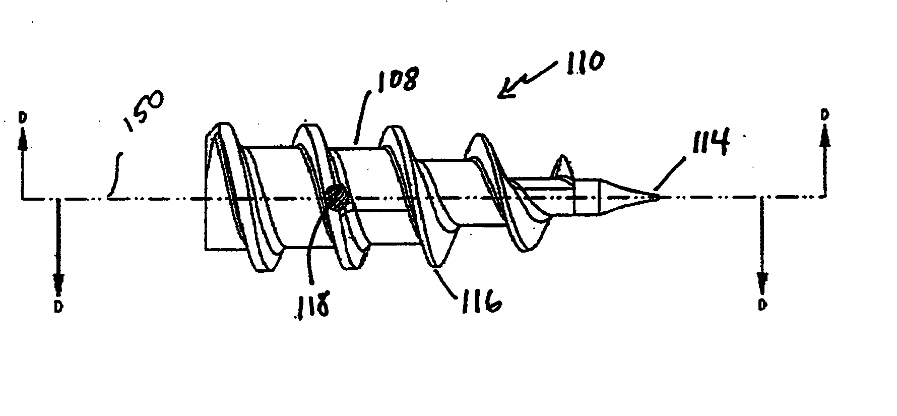
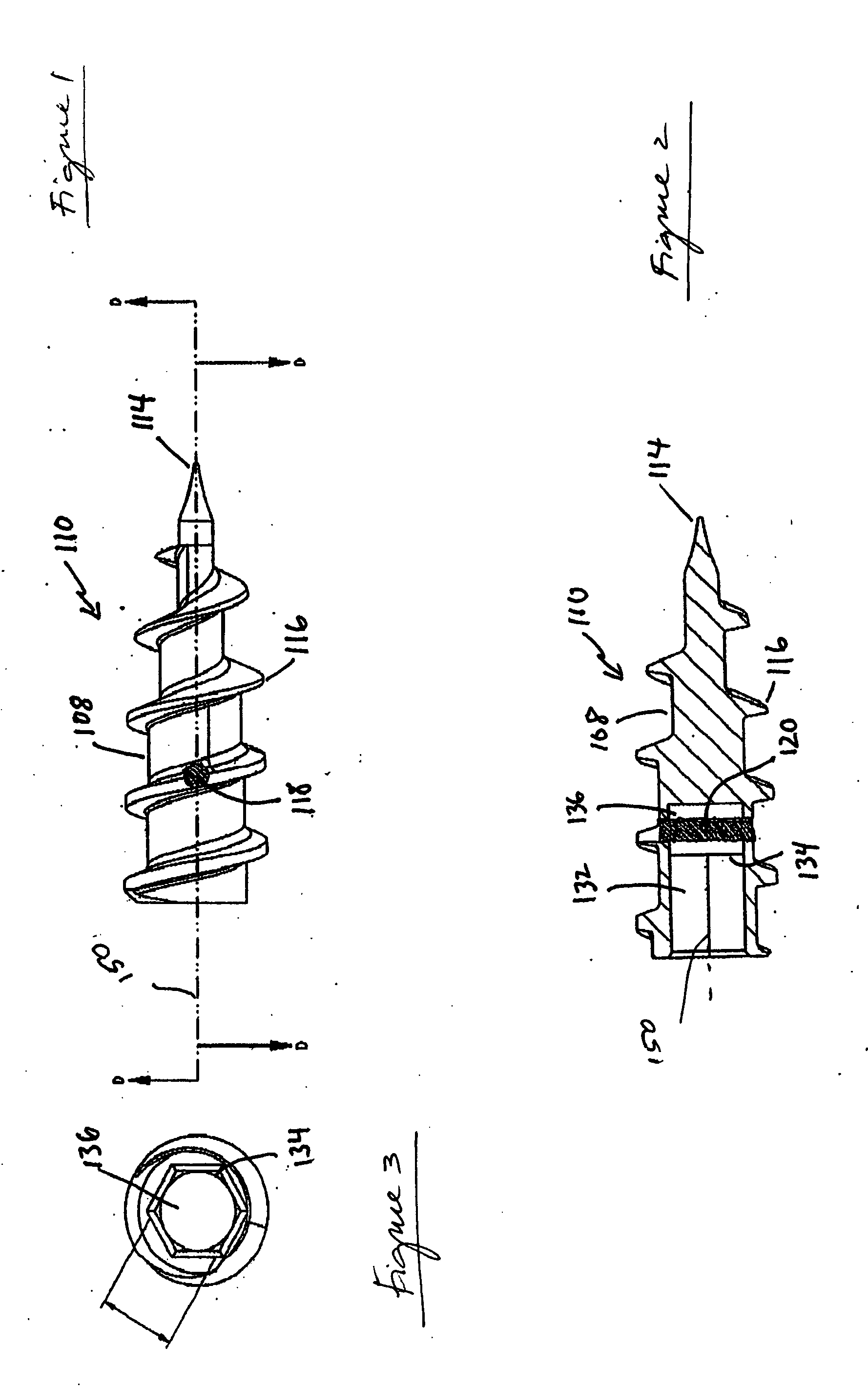
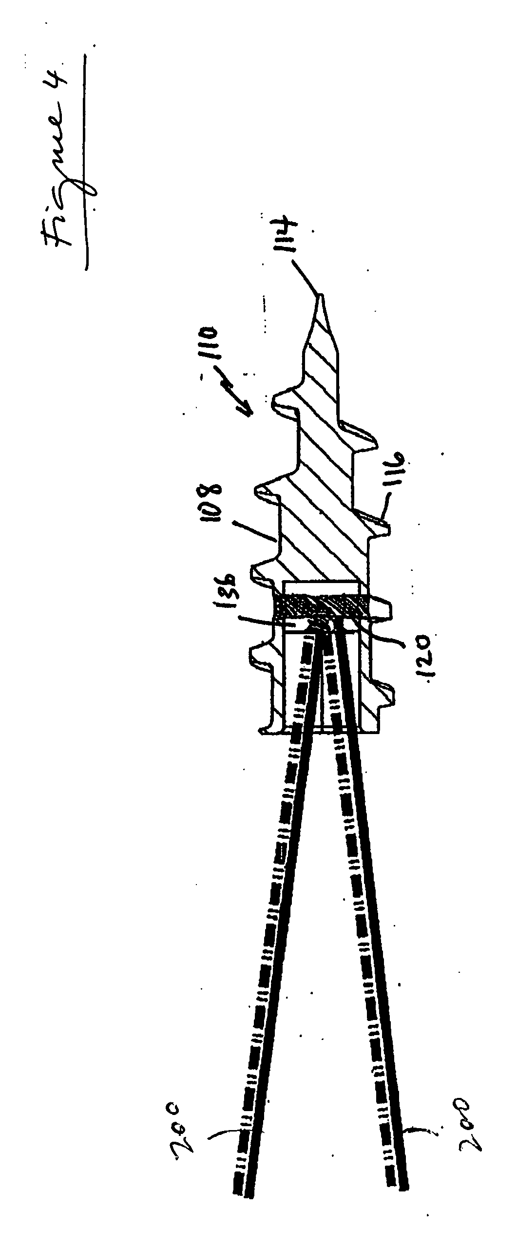
[0023]FIG. 1 illustrates a suture anchor according to a first preferred embodiment of the present invention, indicated generally by reference numeral 110. In the preferred embodiment, body 108 of anchor 110 generally tapers to a narrow point 114 at the distal end thereof. In particular, the major diameter of the anchor body is generally constant along about two-thirds of the length of the body, whereupon the diameter of the anchor then tapers to a relatively sharp point, e.g., approximately 16°. The relatively sharp distal tip of anchor 110 enables ...


PUM

PropertyMeasurementUnit
Angleaaaaaaaaaa
Lengthaaaaaaaaaa
Angleaaaaaaaaaa

Abstract

A suture anchor has a pin that is disposed transversely within the suture anchor, over which one or more strands of suture is looped. The anchor body is threaded and has a tapered distal portion. The proximal end portion of the suture anchor body has a hexagonally shaped opening to accept a hexagonal drive head. The peripheral surface defining hexagonally shaped opening is rounded and smooth to prevent abrading sutures placed in contact therewith.

Description

[0001] This application claims the benefit of U.S. Provisional Application No. 60 / 559,425, filed Apr. 6, 2004, the entire disclosure of which is incorporated by reference herein.FIELD OF THE INVENTION [0002] The present invention relates to an apparatus for anchoring surgical suture to bone. More specifically, the present invention relates to a fully threaded suture anchor provided with a transverse anchor pin for securing, within the anchor, one or more strands of suture to anchor the suture to bone during arthroscopic surgery. [0003] When soft tissue tears away from bone, reattachment becomes necessary. Various devices, including sutures alone, screws, staples, wedges, and plugs have been used in the prior art to secure soft tissue to bone. [0004] Recently, various types of threaded suture anchors have been developed for this purpose. Some threaded suture anchors are designed to be inserted into a pre-drilled hole. Other suture anchors are self-tapping. [0005] U.S. Pat. No. 4,632,...

Claims


Application Information

Patent Timeline
IPC IPC(8): A61B17/04
CPCA61B17/0401A61B2017/0414Y10T29/49947A61B2017/0409A61B2017/044
Inventor DREYFUSS, PETER J.BENAVITZ, WILLIAM C.
Owner ARTHREX
Learn More