
Optical fiber and evaluation method thereof

a technology of optical fiber and evaluation method, applied in the field of optical fiber, can solve the problem of not clearly showing the relation, and achieve the effect of high reliability of the hydrogen-proof characteristi

Inactive Publication Date: 2005-10-06
FURUKAWA ELECTRIC CO LTD
View PDF1 Cites 3 Cited by
  • Summary
  • Abstract
  • Description
  • Claims
  • Application Information

AI Technical Summary

Benefits of technology

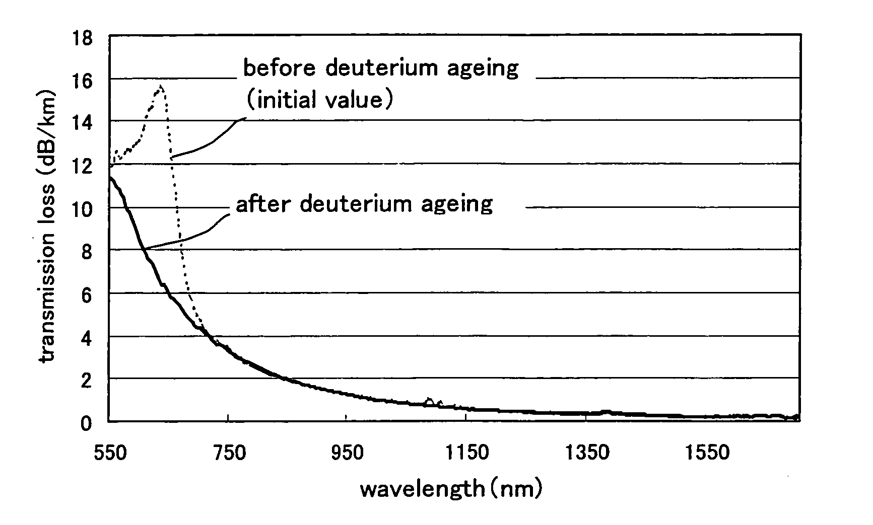
[0025] Up to now, various optical fibers are proposed as optical fibers suitable for WDM transmission in 1310 nm-1625 nm, wherein the transmission loss at 1385 nm mainly due to OH absorption is suppressed and they have excellent hydrogen-proof characteristic. Moreover, the technology of deuterium ageing of the optical fibers is indicated as a method of decreasing the NBOHC density in the optical fiber.
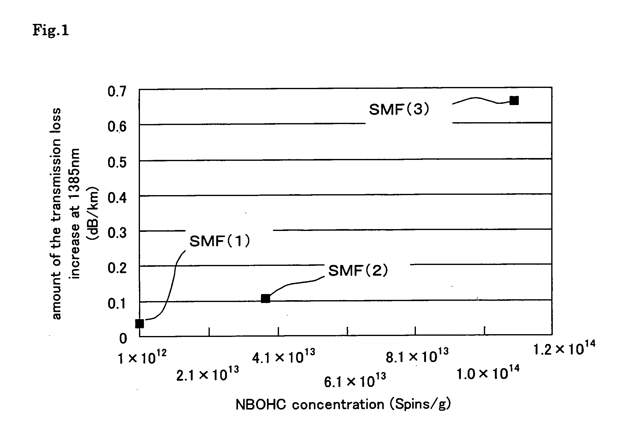
[0029] The purpose of the present invention is to offer an optical fiber which has high reliability of the hydrogen-proof characteristic suitable for the WDM transmission in 1310 nm-1625 nm by clarifying the relation between the NBOHC density in the optical fiber and the amount of an increase of the transmission loss at the wavelength of 1385 nm and finding that the signal of Si(D)-E′ and / or Ge(D)-E′ is detected from the optical fiber to which the deuterium ageing was carried out. In addition, the purpose of the present invention is to offer a method of evaluating the hydrogen characteristic of the optical fiber and whether sufficient deuterium ageing was carried out.

Problems solved by technology

However, there is no report to clearly show the relation between the amount of an increase of the transmission loss at the wavelength of 1385 nm after hydrogen ageing and the NBOHC density in the optical fiber.

Method used


Image

  • Optical fiber and evaluation method thereof
  • Optical fiber and evaluation method thereof
  • Optical fiber and evaluation method thereof

Examples


example

[0060] The optical fiber of the present invention is explained in detail by using the embodiments as follows.

A. Manufacture of Optical Fibers

1. The Targeted Optical Fiber for Manufacture

[0061] The targeted optical fiber for manufacture is assumed to be single mode optical fiber (SMF), that has zero dispersion wavelength in the 1.31 μm band.

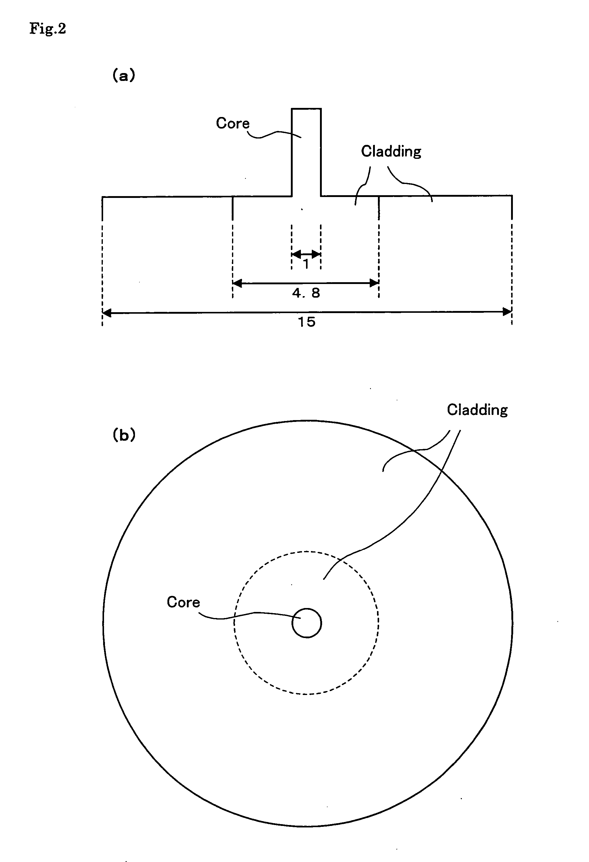
[0062] The general refractive index profile of the step index type core surrounded by the cladding as shown in FIG. 2(a), was adopted in the present embodiment, though the optical fiber of the present invention can be made with a variety of refractive index profiles.

2. Manufacture of Optical Fiber Preform

[0063] The optical fiber preform was manufactured by the VAD (Vapour-phase Axial Deposition) method as shown in FIG. 3, as follows.

[0064] SiCl4 and GeCl4, the raw material of the silica glass, were charged to the first burner 1 in the state of the vapor phase along with H2 and O2, and glass particles doped with Ge were generated by the f...


PUM

PropertyMeasurementUnit
diameteraaaaaaaaaa
wavelengthaaaaaaaaaa

Abstract

An optical fiber characterized by a cutoff wavelength of 1310 nm or less, a transmission loss of 0.40 dB / km or less at the wavelength of 1385 nm before hydrogen ageing, a transmission loss of 0.40 dB / km or less in the wavelength range of 1310 nm to 1625 nm after hydrogen ageing, and an electron spin density of the Non-Bridging Oxygen Hole Center of 1×10¹³ spins / g or less measured by the electron spin resonance method after the diameter of the optical fiber is made to be about 50 μm by etching in diluted hydrofluoric acid, that having high reliability of hydrogen-proof characteristic suitable for WDM transmission in 1310 nm to 1625 nm and the method of evaluating the optical fiber are offered.

Description

FIELD OF THE INVENTION [0001] This invention concerns an optical fiber, which has high reliability of the hydrogen-proof characteristic and is suitable for WDM transmission in 1310 nm to 1625 nm and also the method of evaluating the optical fiber. BACKGROUND OF THE INVENTION [0002] In recent years, research on the Wavelength Division Multiplexing (WDM) transmission is very active and a lot of investigations are also performed to obtain an optical fiber suitable for this WDM transmission. The optical fiber used for the WDM transmission is required to have a low loss in the whole wavelength range to be used. [0003] Though, up to now, the WDM transmission has been examined around 1.55 μm band, wherein the transmission loss of the silica glass optical fiber is the lowest, the further expansion of the transmission capacity is demanded. Therefore, attempts are made to expand the used wavelength range to 1310 nm-1625 nm. [0004] On the other hand, the OH group, which causes the absorption p...

Claims


Application Information

Patent Timeline
Patent Type & Authority Applications(United States)
IPC IPC(8): C03B37/027C03C25/60G02B6/02
CPCC03B37/027C03B2205/42G02B6/02C03C25/607C03B2205/72
Inventor KURUSU, KAZUHIKOMORIDAIRA, HIDEYAKUWABARA, MASAHIDEISHIDA, YOSHINORI
Owner FURUKAWA ELECTRIC CO LTD
Learn More