
Closed end type coiled spring with reduced initial deflection

a closed-end type, spring technology, applied in the direction of resilient suspensions, suspensions, vehicle components, etc., can solve the problems of inability to carry out this method in some application cases, disadvantages of closed-end type coil springs, etc., to prevent the occurrence of initial deflection, reduce the amount of initial deflection thereof, and the effect of the same spring characteristics

Inactive Publication Date: 2005-10-06
NETUREN CO LTD +1
View PDF5 Cites 12 Cited by
  • Summary
  • Abstract
  • Description
  • Claims
  • Application Information

AI Technical Summary

Benefits of technology

The present invention provides a coil spring of closed-end type that decreases in initial deflection as compared to a coil spring of open-end type. This is achieved by using a coupler to transmit force from the terminal portion of the coil spring to the subsequent convolution of the coil spring. The coupler is fixedly mounted on the coil spring to keep the spring constant from the beginning of application of a compression force. The coupler is made of elastic material and can be bonded or held in the coil spring with resiliency. The technical effect of this invention is to reduce the amount of initial deflection of the coil spring, which results in substantially the same spring characteristics as the coil spring of open-end type and reduces manufacturing costs.

Problems solved by technology

Consequently, this type of the coil spring is disadvantageous in that it is necessary for the coil spring to use a special washer such as one disclosed in the Japanese Patent application Laid-open No.
In this respect, the coil spring of the closed-end type is disadvantageous.
However, in this method, since the coil spring is substantially decreased in coil height in installation, it is not possible to carry out this method in some application cases.

Method used


Image

  • Closed end type coiled spring with reduced initial deflection
  • Closed end type coiled spring with reduced initial deflection
  • Closed end type coiled spring with reduced initial deflection

Examples


Embodiment Construction

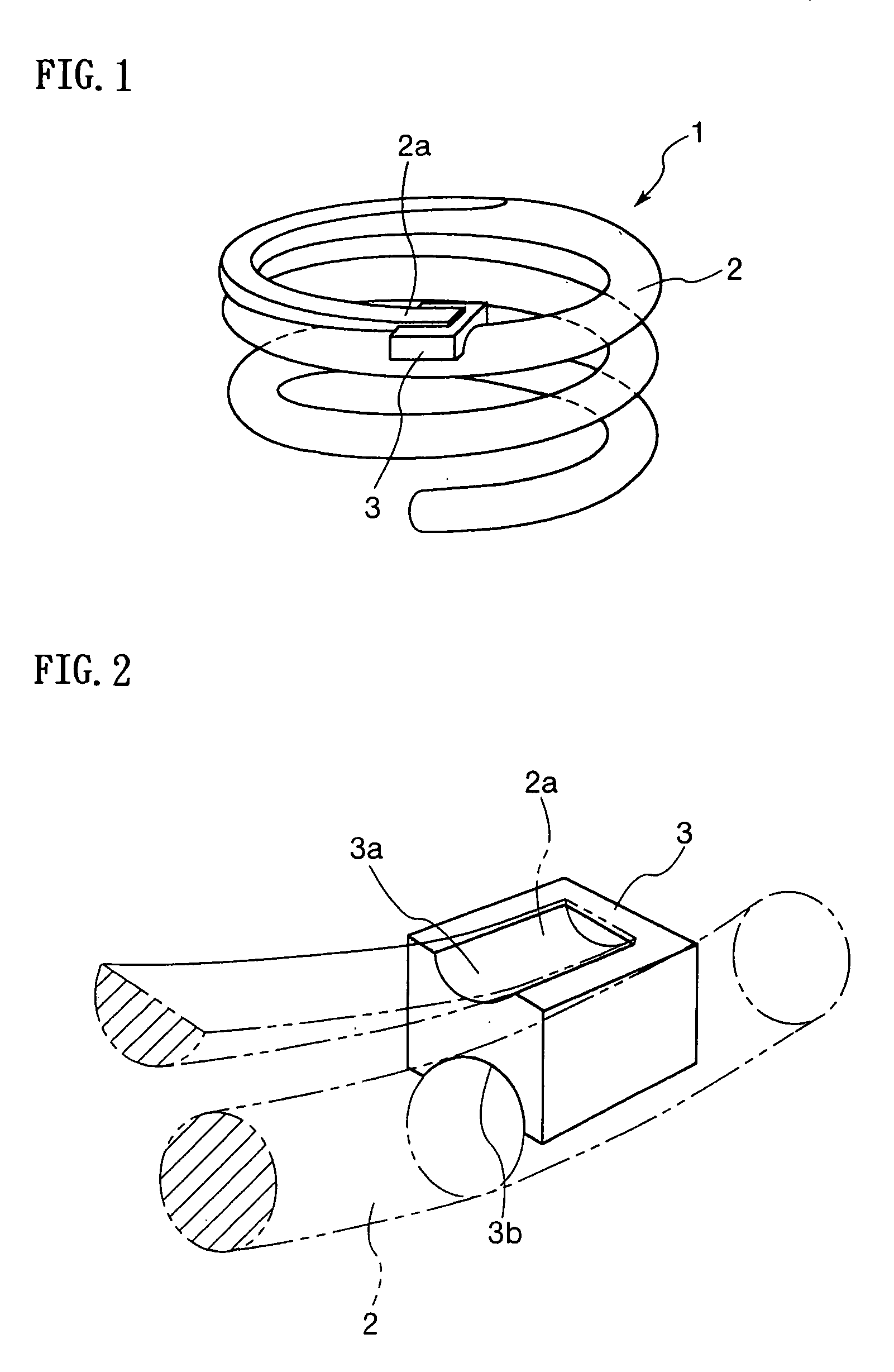
[0024] An embodiment of the present invention, which embodiment is illustrated in the drawings, will be hereinbelow described in a concrete manner. FIG. 1 is a perspective view of a coil spring of closed-end type according to an embodiment of the present invention. FIG. 2 is a perspective view describing an example of a coupler of the present invention.

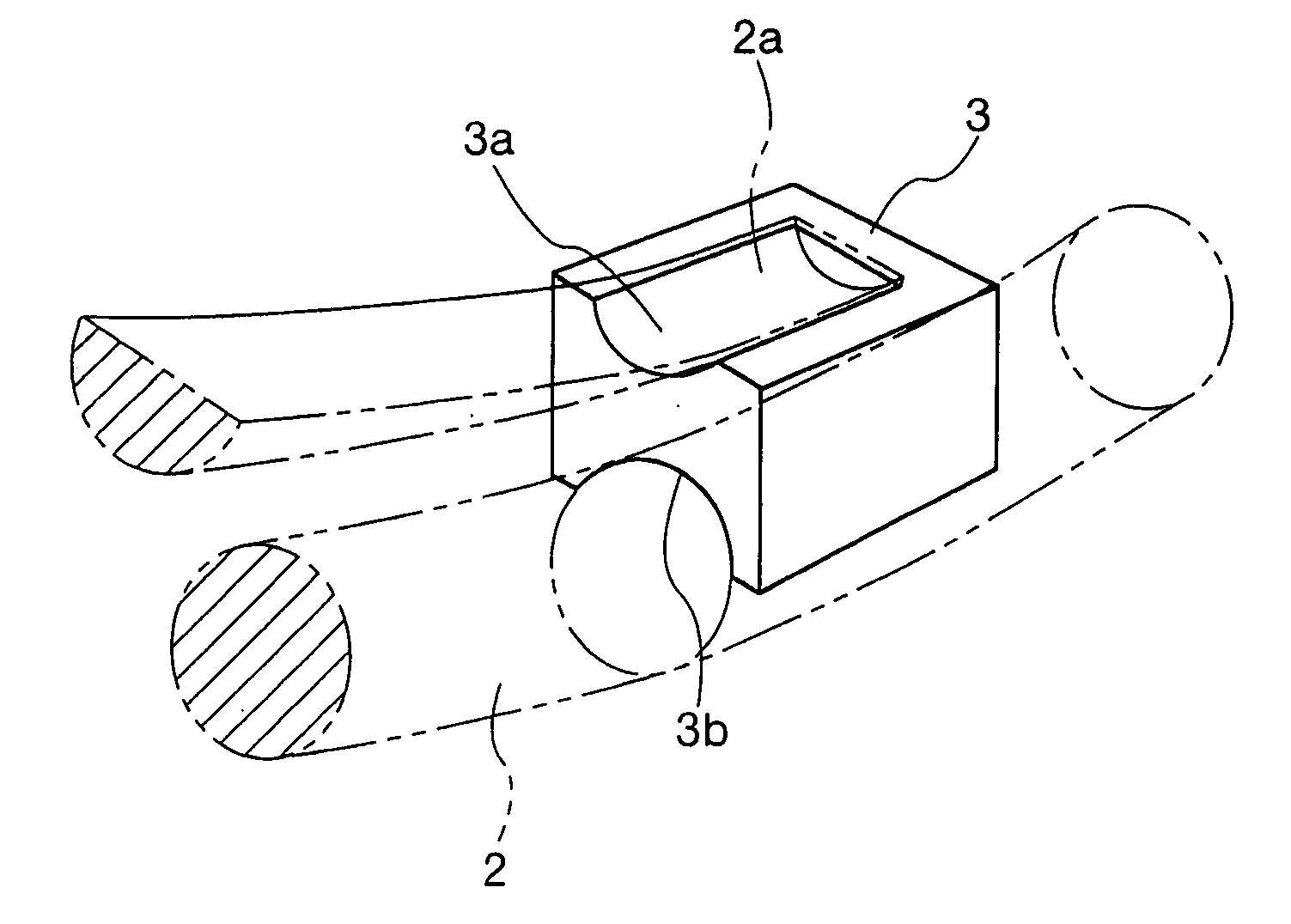
[0025] In FIG. 1, a coil spring of closed-end type of the present invention is constructed of: a coil element rod 2 having each of its opposite coil terminal portions subjected to a surface-flattening process; and, a coupler 3 fixedly mounted on each of the opposite terminal portions 2a of the coil element rod 2, which terminal portions 2a are disposed in the vicinities of opposite ends of the coil element rod 2 (in FIG. 1: only one of the opposite ends of the coil element rod 2 is illustrated; and, the other is not omitted in the drawing.).

[0026] As shown in detail in FIG. 2, an example of the coupler 3 of the present invention is ...


PUM


Abstract

In a coil spring of closed-end type, the coil spring is characterized in that a coupler is fixedly mounted between: an outer peripheral surface of a terminal convolution of a coil element rod; and, an outer peripheral surface of a subsequent convolution subsequent to the terminal convolution of the coil spring of closed-end type, whereby an amount of initial deflection is decreased.

Description

TECHNICAL FIELD [0001] The present invention relates to a coil spring used in a buffer spring and like components of an automobile. BACKGROUND ART [0002] In order to improve an automobile and a bicycle in riding comfort in response to a road condition, a large number of inventions have been disclosed with respect to a coil spring for supporting a vehicle body. For example, in a coil spring described in both Japanese Utility Model application Laid-open No. Sho 56-20140 and Japanese Patent Publication No. Hei 2-22252, an elastic spacer is mounted in an intermediate portion of a coil element rod of the coil spring in order to change a coil constant in response to a road condition. [0003] In a coil spring described in Japanese Utility Model application Laid-open No. Sho 57-113739, a coiled spacer provided with an appropriate number of convolutions is inserted into a proximal terminal portion of the coil spring, so that the number of effective or active convolutions of the coil spring is...

Claims


Application Information

Patent Timeline
Patent Type & Authority Applications(United States)
IPC IPC(8): F16F1/06F16F1/13
CPCF16F1/13
Inventor SOGA, EIICHIARAI, YOSHIAKIYOKOTA, KEISUKE
Owner NETUREN CO LTD
Learn More