
Magnet based angular force control

Inactive Publication Date: 2005-10-06
DAKA RESEARCH INC
View PDF5 Cites 19 Cited by
  • Summary
  • Abstract
  • Description
  • Claims
  • Application Information

AI Technical Summary

Benefits of technology

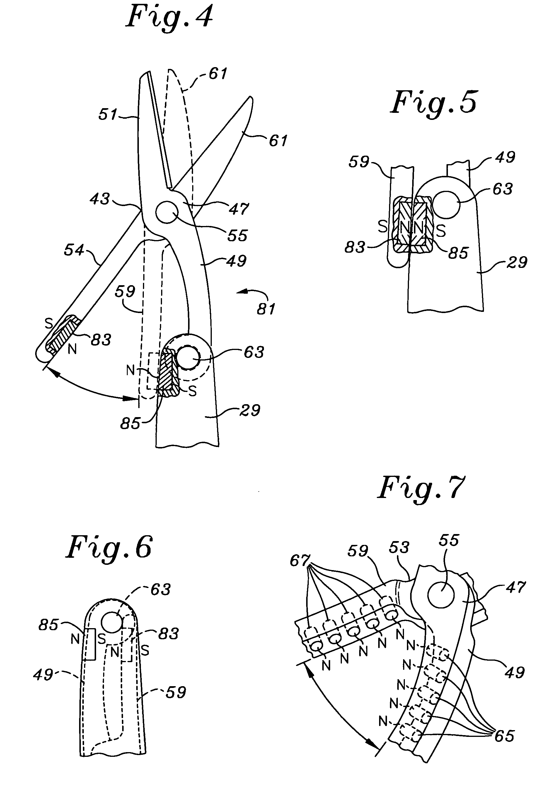
[0012] External magnetic field availability can be used for direction finding, drywall nail location, and other uses which may be enhanced by string, line or cord suspension of the multi-tool containing the magnetic operable angularly displaceable members. Where the magnetic operable angularly displaceable members can be stowably re-oriented to a same, attractive, rather than opposing orientation, the stowed multi-tool will have enhanced magnetic capability, mutually stabilizing magnetic storage capability, and increased stability in the stowed position.
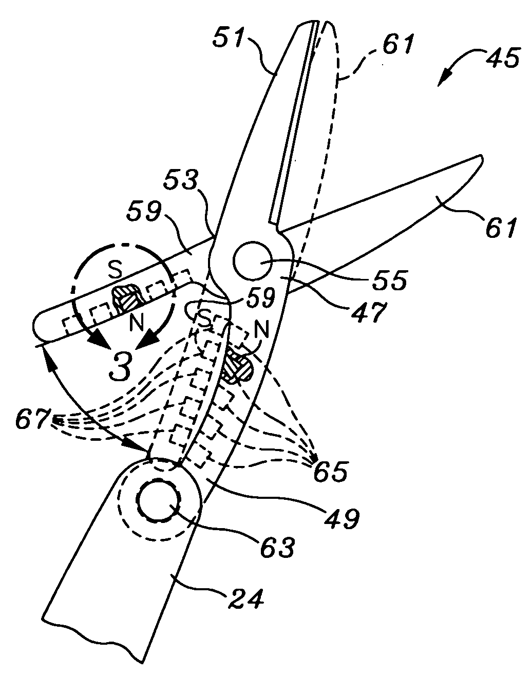
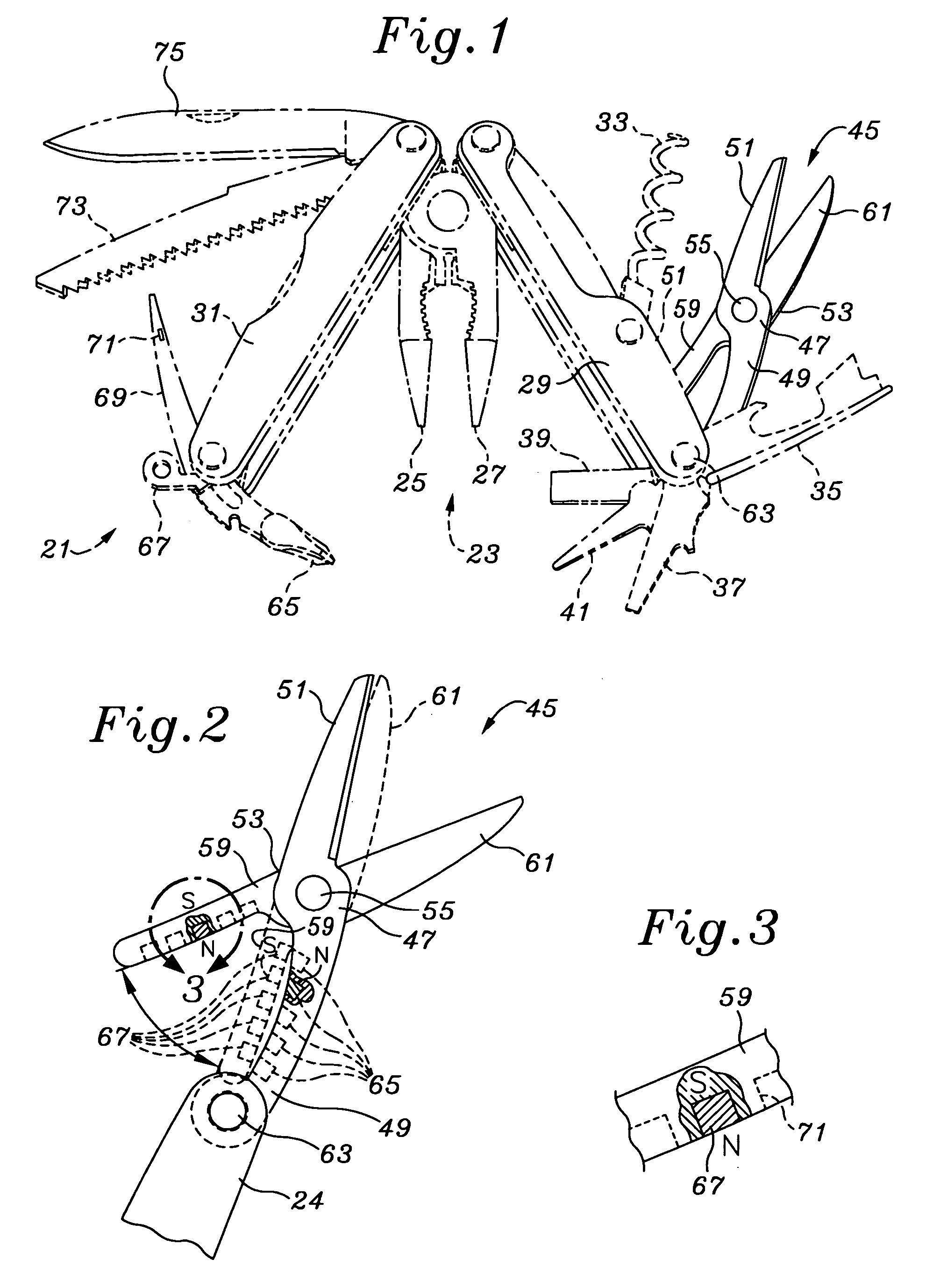
[0013] In one embodiment, the magnets can be provided as a series of inserts within the base of the jaws on the opposite side of the pivot than the blades. In another embodiment, one of the two poles can be provided in the tool body. In both cases, because the repelling forces do not require exact alignment as in the case of a spring, there is an opportunity to offset the magnet locations in any direction. Further, the use of magnets in scissors enables the scissors to be used as a magnetic cleanup tool, magnetic retrieval device, or magnetic attachment and storage.

Problems solved by technology

However, where factors are added to scissors and scissor-like implements including (1) miniaturization, (2) expanded foldability to enable stowage and (3) limited ability for full “fingers versus thumb” action, the ability to use conventional spring structures is seriously challenged.
The use of a spring link can interfere with stowage and retrieval.
A spring link can be caught on other objects and easily bent or damaged.
The provision of spring action in a safe manner and in a way without causing damage to the mechanism has been challenging.

Method used


Image

  • Magnet based angular force control
  • Magnet based angular force control
  • Magnet based angular force control

Examples


Embodiment Construction

[0022] A multi-tool 21 is shown in FIG. 1. In one of the more popular styles, a central pliers set 23 has a first jaw 25 and second jaw 27, is provide between a pair of housing or handle members 29 and 31. To complete the multi-tool, handle 29 is associated with a corkscrew 33, bottle opener 35, flat head screw driver 37, flat head screw driver 39, and pick 41.

[0023] A scissors set 45 is provided having a member 47 having a handle portion 49 attached to the multi-tool 21 handle 28 and continuous with a cutting jaw 51. A member 53 has a pivot 55 attaching it to member 47. Member 53 has a handle portion 59 continuous with a cutting jaw 61. The scissors set 45 is not shown in its most extended position, where it would assume an operational position. Scissors set 45 pivots about a pivot 63 to enable it to be stowed at least partially within the handle 29. Stowage can be performed generally in either direction with the scissors set 45 being stowed with the cutting jaws 51 and 61 closed ...


PUM


Abstract

A scissors set includes magnetic elements to provide the force to open the scissor members, and are particularly useful for miniature, multi-tool use. The scissors disclosed herein use magnets to provide the force of separation. Opposing same-polarity magnets provide high force when in proximity to each other and lower force once angular separation of the opposing jaws have begun. In one embodiment, the magnets can be provided as a series of inserts within the base of the jaws on the opposite side of the pivot than the blades. In another embodiment, one of the two poles can be provided in the tool body. In both cases, because the repelling forces do not require exact alignment as in the case of a spring, there is an opportunity to offset the magnet locations in any direction. Further, the use of magnets in scissors enables the scissors to be used as a magnetic cleanup tool, magnetic retrieval device, or magnetic attachment and storage.

Description

FIELD OF THE INVENTION [0001] The present invention relates to the field of tools and more particularly to the provision of counter force to scissors, pliers or other angular displacement mechanisms and which is especially advantageous in cases where miniaturization results in limited space is availability, a more limited manual manipulation capability and where ancillary magnetic characteristics can provide additional advantages and uses. BACKGROUND OF THE INVENTION [0002] In larger displaceable tools, particularly scissors, the provision of a biasing force is advantageous. For very tiny pliers, the provision of an opening force which is counter to the manual grasping force can enable users in tight spaces to more exactly manipulate the tool without the need for re-positioning of the hands in order to open the tool. This is also particularly the case for scissors in which rapid movement over a narrow angle displacement is advantageous. [0003] In larger scissors, a spring provided c...

Claims


Application Information

Patent Timeline
IPC IPC(8): B25F1/00B26B13/00B26B13/22
CPCB26B13/22B25F1/003
Inventor MAH, PAT Y.
Owner DAKA RESEARCH INC
Learn More