
High voltage outdoor substation

a substation and high-voltage technology, applied in the direction of substations, non-enclosed substations, switchgear with withdrawn carriage, etc., can solve the problem that a single maintenance period requires only a short time period

Inactive Publication Date: 2005-09-29
ABB POWER GRIDS SWITZERLAND AG +1
View PDF6 Cites 7 Cited by
  • Summary
  • Abstract
  • Description
  • Claims
  • Application Information

AI Technical Summary

Benefits of technology

[0006] The invention, as it is defined in the patent claims, achieves the object of specifying a substation of the type mentioned initially, which can be produced at low cost and is nevertheless distinguished by high availability.
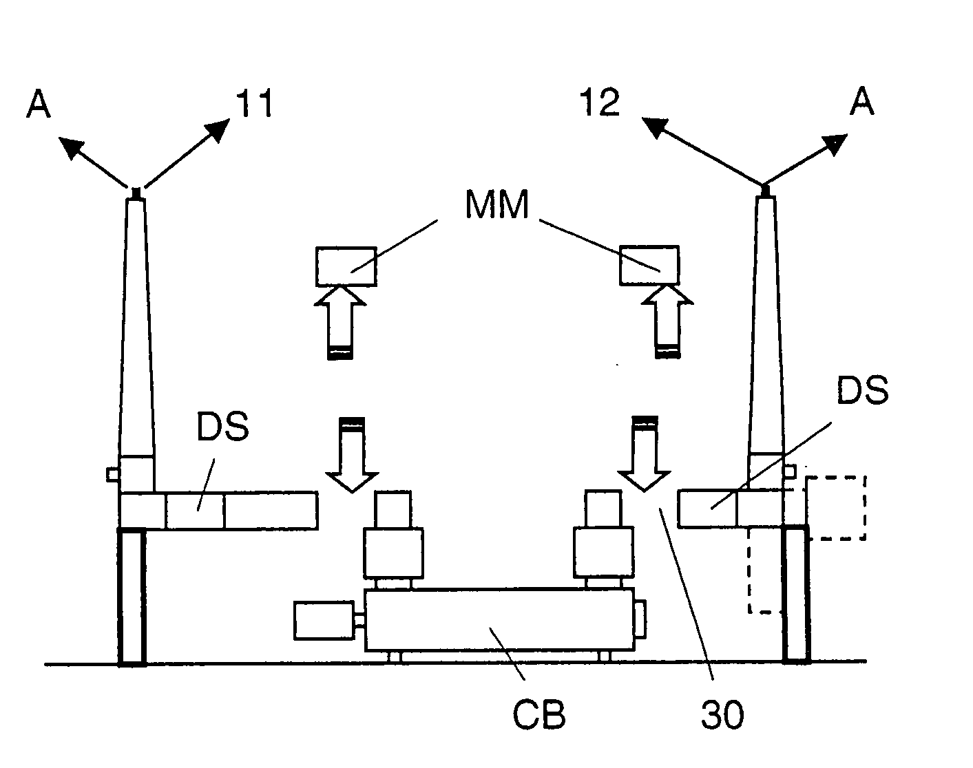
[0007] In the substation according to the invention, an installation module which allows lateral removal of at least one of the two switchgear modules is arranged between a disconnector module and a circuit breaker module in the encapsulated switchgear arrangement. A highly stressed component of the encapsulated switchgear arrangement, that is to say the disconnector module or the circuit breaker module, can thus be removed by lateral removal from the substation without having to change the position of the other component. Once the removed component has been replaced, the complete availability of the substation can be reproduced quickly and at low cost within a few hours. This therefore avoids long down times—as in the case of conventionally designed gas-insulated switchgear arrangements. Since individual components can be removed selectively from the switchgear arrangement, which is typically connected to a branch circuit, there is therefore generally no need either to switch off any other branch circuit in the relevant switch bay, or any busbar which relates to the entire substation. All safety separations can be complied with by means of suitably arranged grounding apparatuses. There is no need for any additional protective measures for replacement of the component to be replaced.
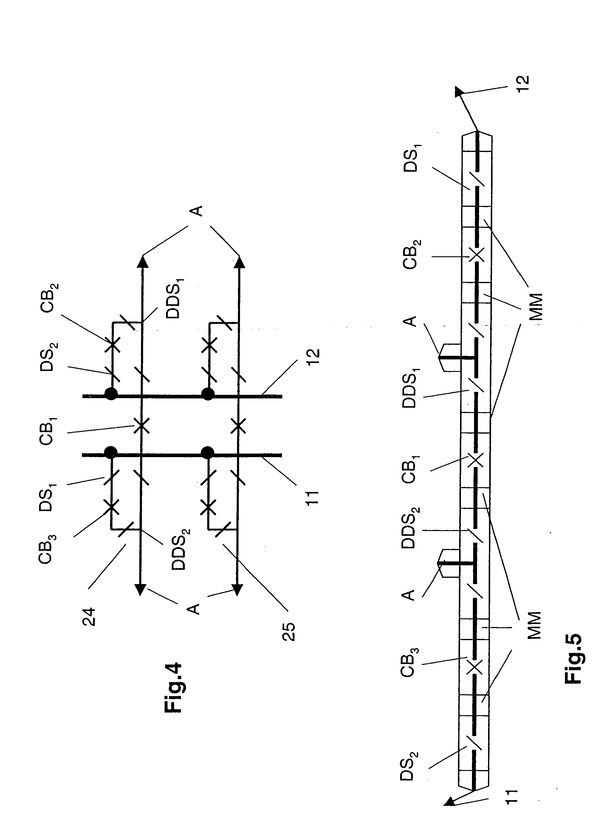
[0008] If the substation according to the invention has at least two outdoor busbars as well as an encapsulated circuit arrangement which is in the form of a cross-coupling and in which a first disconnector module is connected to a first of the two busbars and a second disconnector module, which is connected to the circuit breaker module, is connected to the second busbar, then it is recommended that a second installation module, which allows lateral removal of the circuit breaker, be arranged between the second disconnector module and the circuit breaker module. The use of two installation modules allows the circuit breaker module to be removed laterally without any shifting, at right angles to the removal direction.
[0010] In a further embodiment of the substation according to the invention having at least two outdoor busbars and having at least two switchgear arrangements which are arranged in different switch bays to one another and each of which contains at least one branch circuit, the switchgear arrangements should have different switchgear configurations, and at least one of the switchgear configurations should be encapsulated and gas-insulated. Thanks to the space-saving design of the encapsulated, gas-insulated switchgear arrangement, existing outdoor substations can thus easily be converted, and existing branch circuits can be connected by means of differently designed and / or differently arranged switchgear arrangements to the busbars, which ensure particularly high availability or only less high availability depending on the requirement.

Problems solved by technology

However, a lengthy down time must be planned for maintenance on one of these switchgear arrangements, quite in contrast to a comparable outdoor switchgear arrangement in which, although maintenance work must admittedly be carried out more frequently, a single maintenance period requires only a short time period, however, since defective outdoor components can be replaced relatively quickly.

Method used


Image

  • High voltage outdoor substation
  • High voltage outdoor substation
  • High voltage outdoor substation

Examples


Embodiment Construction

[0006] The invention, as it is defined in the patent claims, achieves the object of specifying a substation of the type mentioned initially, which can be produced at low cost and is nevertheless distinguished by high availability.

[0007] In the substation according to the invention, an installation module which allows lateral removal of at least one of the two switchgear modules is arranged between a disconnector module and a circuit breaker module in the encapsulated switchgear arrangement. A highly stressed component of the encapsulated switchgear arrangement, that is to say the disconnector module or the circuit breaker module, can thus be removed by lateral removal from the substation without having to change the position of the other component. Once the removed component has been replaced, the complete availability of the substation can be reproduced quickly and at low cost within a few hours. This therefore avoids long down times—as in the case of conventionally designed gas-i...


PUM


Abstract

The substation has at least one outdoor busbar (11, 12) as well as at least two switch bays which can be connected to the busbar and at least one encapsulated, gas-insulated, arrangement of switchgear modules (30) which is arranged in one of the switch bays. This switchgear arrangement contains at least one disconnector module (DS) and at least one circuit breaker module (CB). An installation module (MM) is arranged between the disconnector module and the circuit breaker module and allows lateral removal of at least one of the two switchgear modules (DS, CB). This substation is distinguished by high availability, since each of the most severely loaded components of the encapsulated switchgear arrangement, that is to say the disconnector module and the circuit breaker module, can be removed from the substation by lateral removal without having to change the position of the other components. Once the removed component has been replaced, the complete substation availability can be reproduced quickly and at low cost.

Description

TECHNICAL FIELD [0001] The invention is based on a high-voltage substation as claimed in the precharacterizing clause of patent claim 1. This substation has at least one outdoor busbar and at least two switch bays or substation sections which can be connected to the busbar. An encapsulated, gas-insulated, arrangement of switchgear modules is provided in one of the switch bays and contains at least one module in the form of an isolator or disconnector, and at least one module in the form of a circuit breaker. [0002] A substation such as this, which is frequently referred to as a hybrid substation, has a terminating structure which covers switch bays and on which an outdoor busbar system as well as branch circuits, such as feeders and load outgoers are generally supported. At least one of the switch bays generally contains a gas-insulated arrangement of switchgear modules which is encapsulated on a single-phase or polyphase basis and which, depending on the configuration, ensures a mo...

Claims


Application Information

Patent Timeline
IPC IPC(8): H02B1/04H02B1/20H02B5/00H02B5/06H02B7/00H02B11/127H02B13/00
CPCH02B5/06
Inventor LANDERT, HANS-PETERFUECHSLE, DIETER
Owner ABB POWER GRIDS SWITZERLAND AG
Learn More