
Methods of isolating hydrajet stimulated zones

a stimulation and stimulation technology, applied in the direction of fluid removal, wellbore/well accessories, sealing/packing, etc., can solve the problems of difficult to control the formation of multi-zone fractures along the wellbore, difficult to casing the hole, and high cost, so as to reduce the cycle time of operation

Active Publication Date: 2005-09-29
HALLIBURTON ENERGY SERVICES INC
View PDF19 Cites 61 Cited by
  • Summary
  • Abstract
  • Description
  • Claims
  • Application Information

AI Technical Summary

Benefits of technology

[0009] An advantage of the present invention is that the tubing string can be inside the wellbore during the entire treatment. This reduces the cycle time of the operation. Under certain conditions the tubing string with the hydrajetting tool or the wellbore annulus, whichever is not being used for the fracturing operation, can also be used as a real-time BHP (Bottom Hole Pressure) acquisition tool by functioning as a dead fluid column during the fracturing treatment. Another advantage of the invention is the tubing string provides a means of cleaning the wellbore out at anytime during the treatment, including before, during, after, and in between stages. Tubulars can consist of continuous coiled tubing, jointed tubing, or combinations of coiled and jointed tubing.

Problems solved by technology

When stimulating a reservoir from a wellbore, especially those that are highly deviated or horizontal, it is difficult to control the creation of multi-zone fractures along the wellbore without cementing a liner to the wellbore and mechanically isolating the zone being fractured from previously fractured zones or zones not yet fractured.
A drawback of this technique, however, is that it requires multiple trips to carry out the various stimulation and isolation steps.
The SURGIFRAC process has been applied mostly to horizontal or highly deviated wellbores, where casing the hole is difficult and expensive.
Thus, prior to the SURGIFRAC technique, methods available were usually too costly to be an economic alternative, or generally ineffective in achieving stimulation results, or both.

Method used


Image

  • Methods of isolating hydrajet stimulated zones
  • Methods of isolating hydrajet stimulated zones
  • Methods of isolating hydrajet stimulated zones

Examples


Embodiment Construction

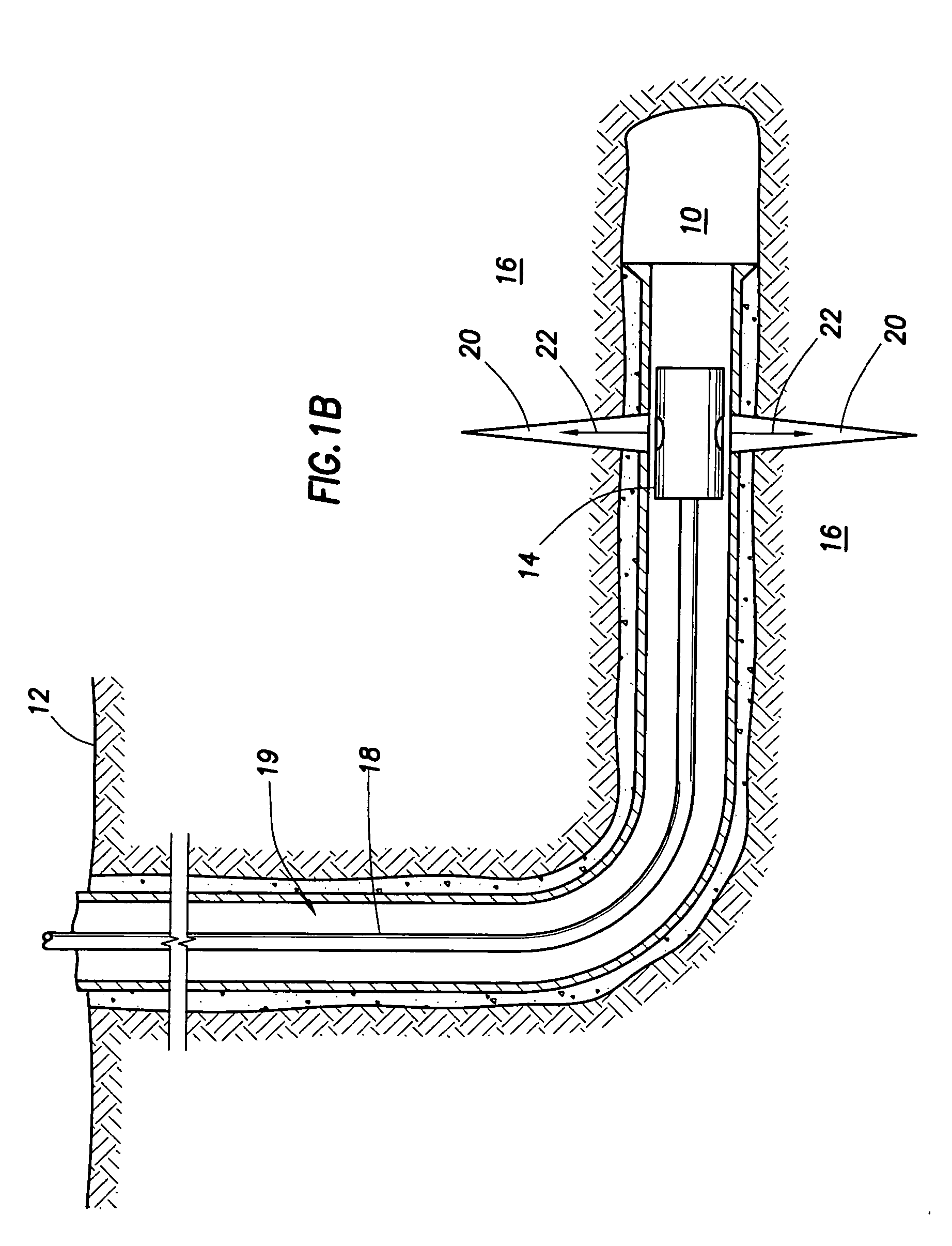
[0026] The details of the method according to the present invention will now be described with reference to the accompanying drawings. First, a wellbore 10 is drilled into the subterranean formation of interest 12 using conventional (or future) drilling techniques. Next, depending upon the nature of the formation, the wellbore 10 is either left open hole, as shown in FIG. 1A, or lined with a casing string or slotted liner, as shown in FIG. 1B. The wellbore 10 may be left as an uncased open hole if, for example, the subterranean formation is highly consolidated or in the case where the well is a highly deviated or horizontal well, which are often difficult to line with casing. In cases where the wellbore 10 is lined with a casing string, the casing string may or may not be cemented to the formation. The casing in FIG. 1B is shown cemented to the subterranean formation. Furthermore, when uncemented, the casing liner may be either a slotted or preperforated liner or a solid liner. Thos...


PUM


Abstract

The present invention is directed to a method of isolating hydrajet stimulated zones from subsequent well operations. The method includes the step of drilling a wellbore into the subterranean formation of interest. Next, the wellbore may or may not be cased depending upon a number of factors including the nature and structure of the subterranean formation. Next, the casing, if one is installed, and wellbore are perforated using a high pressure fluid being ejected from a hydrajetting tool. A first zone of the subterranean formation is then fractured and stimulated. Next, the first zone is temporarily plugged or partially sealed by installing an isolation fluid into the wellbore adjacent to the one or more fractures and / or in the openings thereof, so that subsequent zones can be fractured and additional well operations can be performed.

Description

FIELD OF THE INVENTION [0001] The present invention relates generally to well completion operations, and more particularly methods of stimulation and subsequent isolation of hydrajet stimulated zones from subsequent jetting or stimulation operations, so as to minimize the loss of completion / stimulation fluids during the subsequent well jetting or stimulation operations. BACKGROUND OF THE INVENTION [0002] In some wells, it is desirable to individually and selectively create multiple fractures having adequate conductivity, usually a significant distance apart along a wellbore, so that as much of the hydrocarbons in an oil and gas reservoir as possible can be drained / produced into the wellbore. When stimulating a reservoir from a wellbore, especially those that are highly deviated or horizontal, it is difficult to control the creation of multi-zone fractures along the wellbore without cementing a liner to the wellbore and mechanically isolating the zone being fractured from previously ...

Claims


Application Information

Patent Timeline
IPC IPC(8): E21B43/114E21B43/25E21B43/26
CPCE21B43/114E21B43/261E21B43/25
Inventor WILLETT, RONALD M.SURJAATMADJA, JIM B.MCDANIEL, BILLY W.
Owner HALLIBURTON ENERGY SERVICES INC
Learn More