
Component specific tube banks for hydroforming body structure components

a technology for hydroforming body structure components and components, applied in the field of hydroforming component specific blanks, can solve the problems of increasing reducing the number of parts, and increasing the cost of manufacturing, so as to facilitate the efficient and versatile shaping of automotive body components and reduce the amount of packaging space required

Active Publication Date: 2005-09-29
FORD GLOBAL TECH LLC
View PDF7 Cites 1 Cited by
  • Summary
  • Abstract
  • Description
  • Claims
  • Application Information

AI Technical Summary

Benefits of technology

The present invention provides a method and system for efficiently shaping component specific blanks through hydroforming. The method involves rolling a bow tie shaped blank to form a dual conical tube, which is then inserted into a metal forming device and formed to an approximate shape through pressurization. The system includes a dual conical tube with a smaller cross-sectional area in the central portion and a shaping die that can conform to the blank. The technical effects of this invention include efficient and versatile shaping of automotive body components, a decrease in package space required, and the elimination of the need for additional reinforcements.

Problems solved by technology

The drawback to high pressure forming is that, due to friction, parts tend to have non-uniform thickness.
Improved process flow also tends to result from decreased die wear due to fluid on metal forming rather than metal on metal forming.
Replacing the front stamped rail with a regular tube shape hydroformed rail requires end feeding into a hydroform press to get expansion near the ends during a hydroforming process, and this method of feeding tends to limit the degree of conical shape, which is needed for automobile body engineering requirements.
The limitation associated with current component molding techniques has made it apparent that a modified technique to mold components is necessary.

Method used


Image

  • Component specific tube banks for hydroforming body structure components
  • Component specific tube banks for hydroforming body structure components
  • Component specific tube banks for hydroforming body structure components

Examples


Embodiment Construction

[0021] The present invention is illustrated with respect to a method for molding a component, particularly suited to the automotive field. The present invention is, however, applicable to various other uses that may require hydroformed components, as will be understood by one skilled in the art.

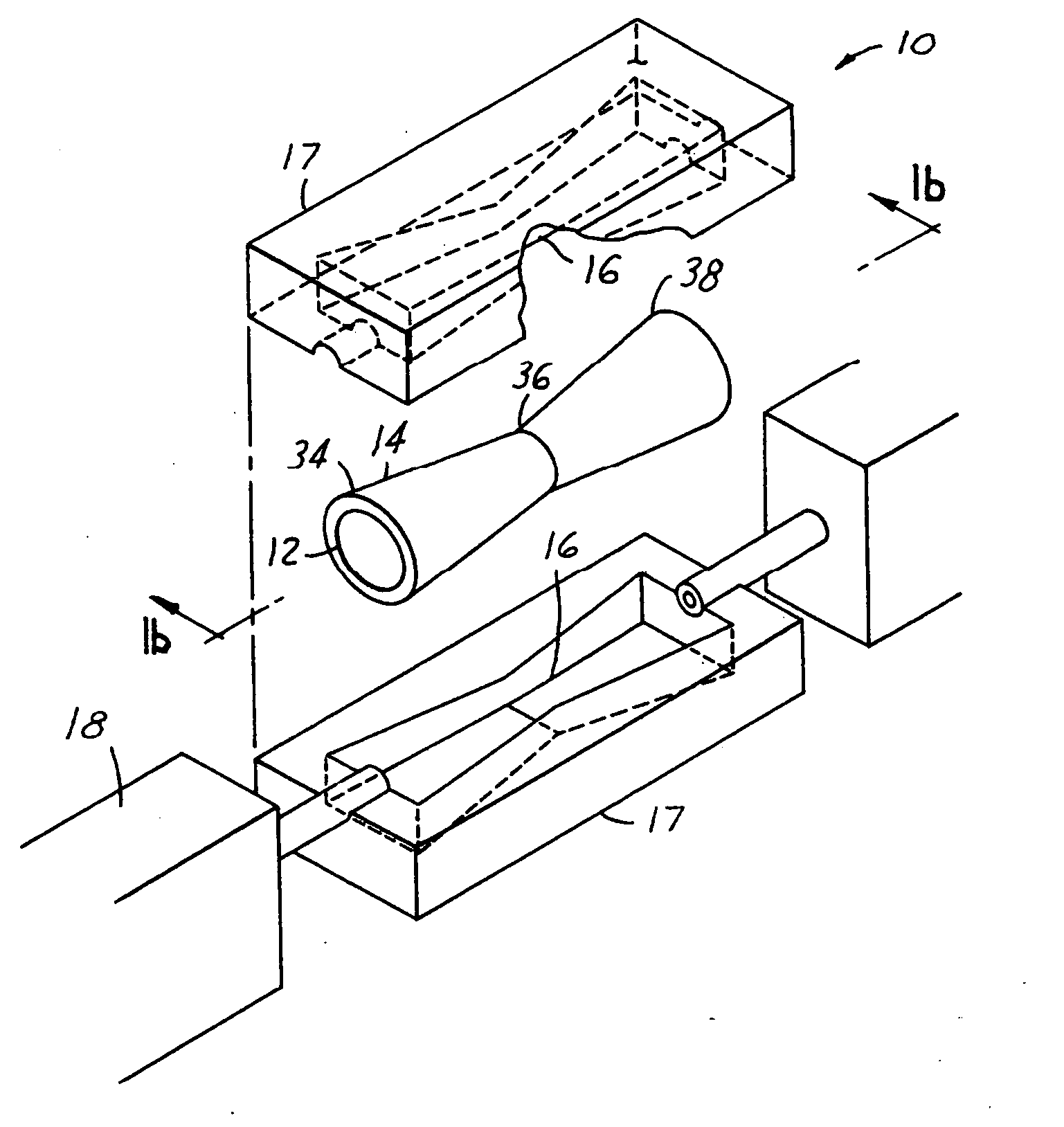
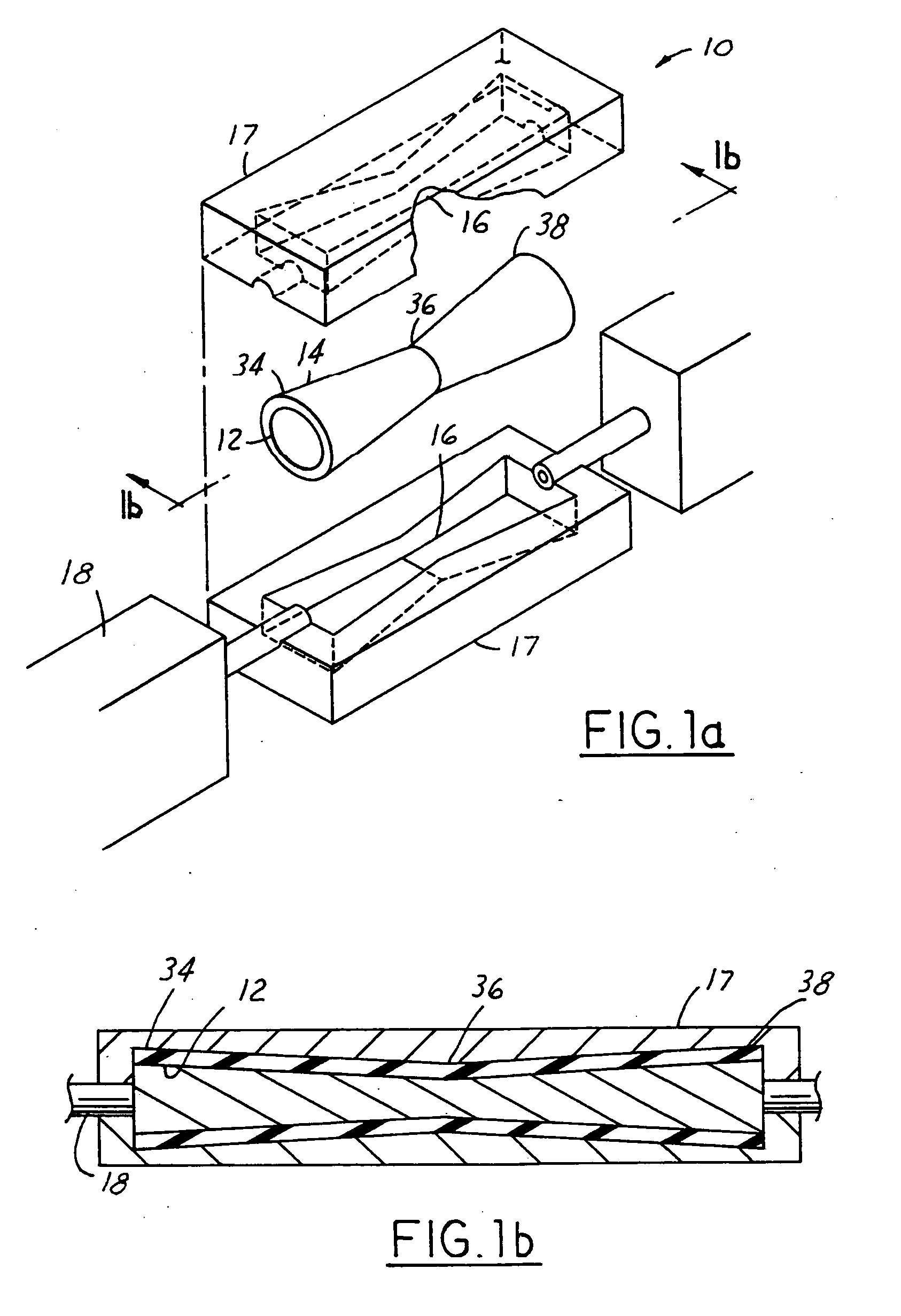
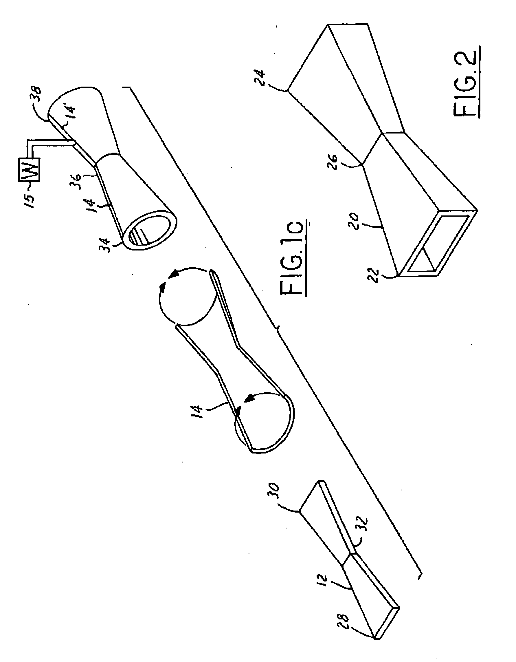
[0022] Referring to FIGS. 1a, 1b, and FIG. 2, a dual conical tube 14 for use in a hydroforming method 10, including a substantially bow tie shaped blank 12, is disclosed. The blank 12 is adapted to be rolled to form the dual conical tube 14. The blank 12 is here illustrated as a substantially bow tie shaped blank 12, however, it is to be understood that numerous alternate blank shapes may be used depending on specific part parameters, as one skilled in the art would realize.

[0023] The substantially bow tie shaped blank 12 is reinforced, depending on material and tensile requirements for the blank 12 prior to the rolling and forming processes, as will be discussed later. Alternate embodiment...


PUM

PropertyMeasurementUnit
cross sectional areaaaaaaaaaaa
pressureaaaaaaaaaa
moldingaaaaaaaaaa

Abstract

A hydroforming system includes a dual conical tube formed from a blank. The dual conical tube has a first end, a second end and a central portion positioned between the first and the second ends. The central portion has a smaller cross sectional area than the first and the second ends. A shaping die is adapted to receive the dual conical tube, and the shaping die is subject to pressurize such that the tube substantially approximates the shape of the shaping die.

Description

TECHNICAL FIELD [0001] The present invention relates generally to processes for molding automotive components and, more particularly, to a method for hydroforming component specific blanks. BACKGROUND ART [0002] Hydroforming is a metal forming process through which metal tube blanks are formed into shapes, such as automotive body components, through the application of internal water hydraulic pressure. [0003] Standard hydroforming techniques start with a sheet of metal or a bent tube. Hydroforming differs from conventional deep drawing processes by replacing die tools with rubber diaphragms, which are backed with fluid pressure, to form punch tool components. [0004] Relating the aforementioned concept to tubular parts, a tube is placed in a die, then the tube is filled with a fluid pressure to form a part to the die. In other words, the tube blanks are reshaped through cross-sectional changes along the length of the tube blanks. [0005] Low pressure sheet forming, through which the t...

Claims


Application Information

Patent Timeline
Patent Type & Authority Applications(United States)
IPC IPC(8): B21D22/10B21D26/02B21D39/20
CPCB21D26/033Y10T29/49805B21D26/047
Inventor COOPER, GEOFFREYJAROCKI, COREYJOAQUIN, ARMANDOPEREZ, CARLOS
Owner FORD GLOBAL TECH LLC
Learn More