
Side vented arc path on network protector rollout

a network protector and side venting technology, applied in the field of network protectors, can solve the problems of no gasses venting place, very undesirable situation,

Inactive Publication Date: 2005-09-22
EATON CORP
View PDF6 Cites 6 Cited by
  • Summary
  • Abstract
  • Description
  • Claims
  • Application Information

AI Technical Summary

Benefits of technology

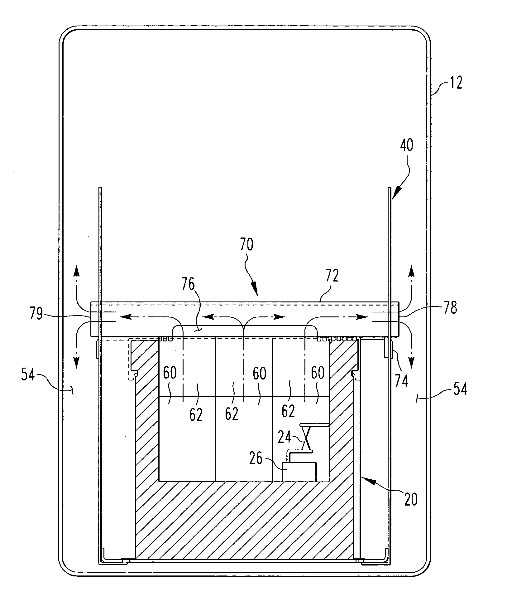
[0012] The hollow member is, preferably, made from a non-conductive material. As such, any residual energy that is not extinguished in the arc chute will dissipate in the arc path assembly. Additionally, the hollow member is, preferably, an elongated member having a longitudinal axis that is generally perpendicular to the axis of each arc chute. As such, the flow path through which the arc gasses travel turns about ninety degrees. This turn in the flow path allows the arc gas particulate matter to collect on the non-conductive hollow member, thereby reducing the chance that deposits of arc gas particulate matter will create a flow path for electricity between the arc chute and other areas of the network protector.

Problems solved by technology

Such a situation is very undesirable.
However, given the limited space within the enclosure, there is no place for the gasses to be vented by the arc chutes that would not effect the circuit breaker or other electrical components.

Method used


Image

  • Side vented arc path on network protector rollout
  • Side vented arc path on network protector rollout
  • Side vented arc path on network protector rollout

Examples


Embodiment Construction

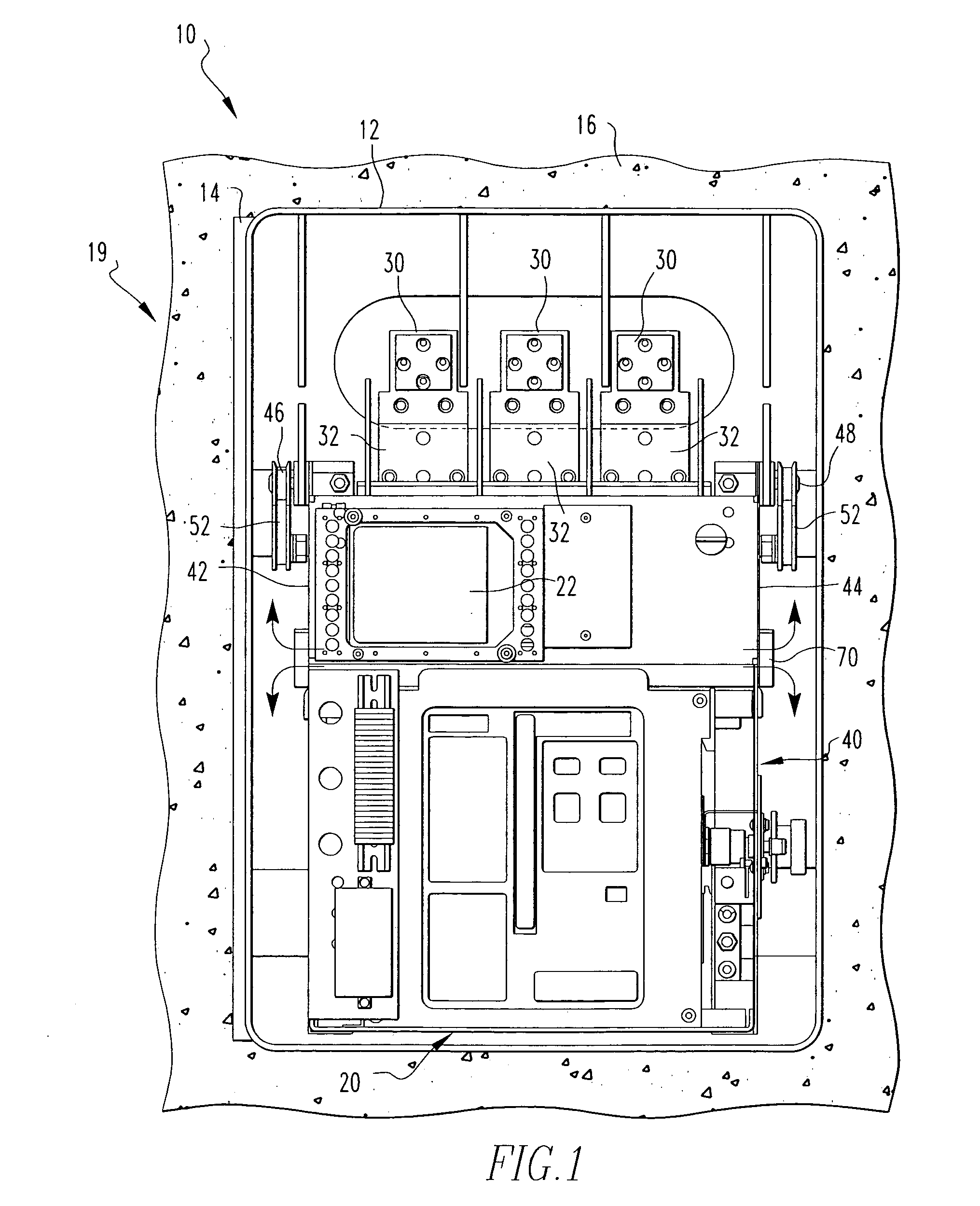
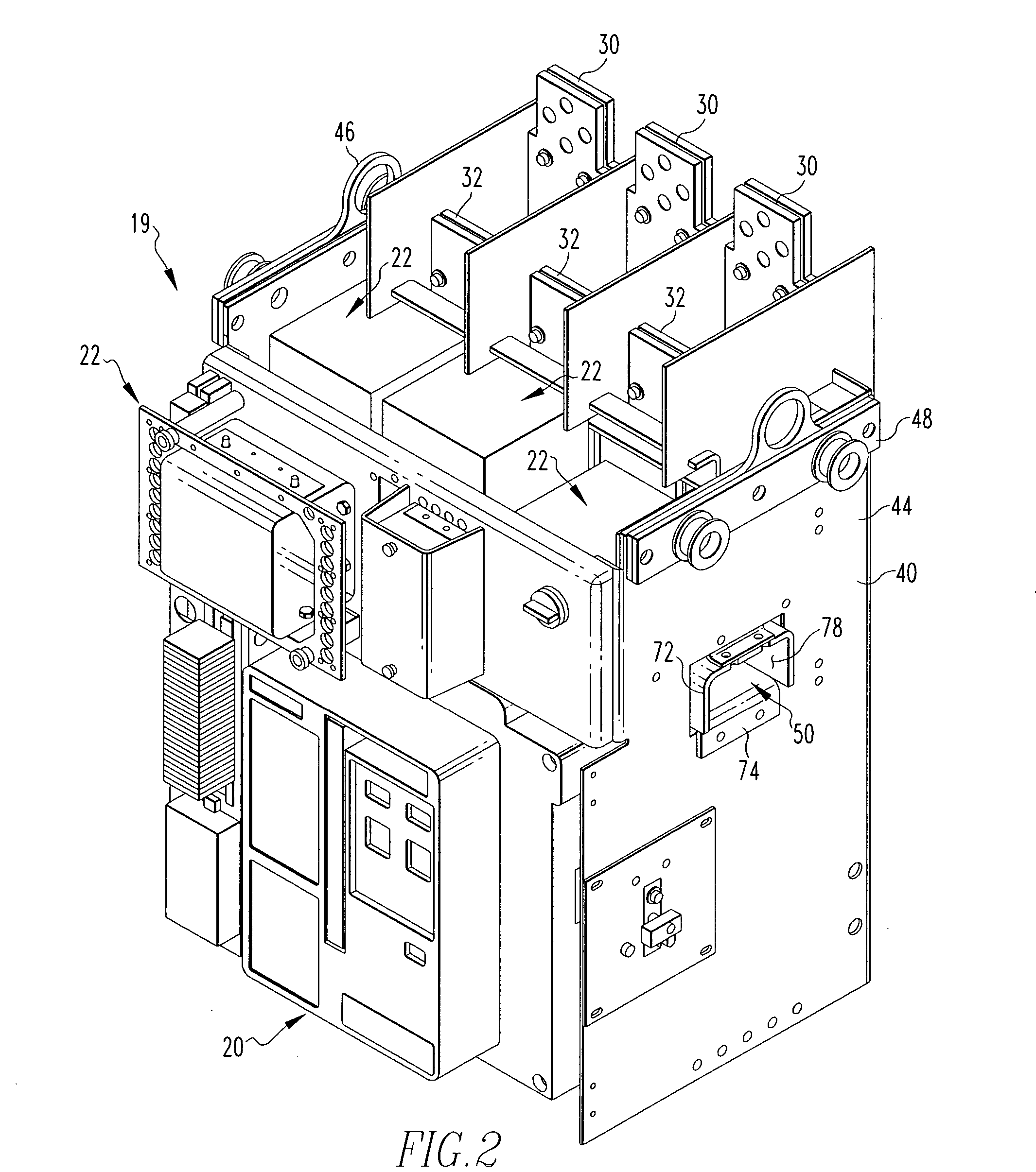
[0017] As shown in FIG. 1, a network protector 10 includes a tank 12 which includes a movable door 14. The tank 12 may be placed within a vault 16. The vault 16 is typically made of concrete or a similar material. The network protector 10 includes a plurality of electrical components 19 such as a circuit breaker 20 as well as other electrical components 22. The plurality of electrical components 19 are coupled, either directly or indirectly, to a frame assembly 40. The frame assembly 40 is structured to move in and out of the tank 12 as described below. The circuit breaker 20 includes at least one set of main contacts 24 (shown schematically, FIG. 3) that are structured to move between a first, open position and a second closed position. When the main contacts 24 are in the second, closed position, electricity may flow through the circuit breaker 20. When the main contacts 24 are in the first, open position, electricity cannot flow through the circuit breaker 20. The circuit breaker...


PUM


Abstract

A network protector that includes an enclosure, a frame assembly, a plurality of electrical components, including a circuit breaker, and an arc path assembly. The frame assembly is disposed within said enclosure. The plurality of electrical components is coupled to the frame assembly. The circuit breaker has at least one set of main contacts and at least one are chute associated with set of main contacts. The arc path assembly has a hollow member having at least one open end. The hollow member in fluid communication with the arc chute and the hollow member open end extends beyond said frame assembly. Thus, arc gasses traveling from the arc chute through the hollow member are exhausted into said enclosure.

Description

BACKGROUND OF THE INVENTION [0001] 1. Field of the Invention [0002] The present invention relates to a network protector and, more specifically, to a network protector having an arc path structured to direct arc gasses away from the network protector electrical components. [0003] 2. Background Information [0004] Secondary power distribution networks consist of interlaced grids which are supplied by two or more sources of power so that the loss of a single source of power will not result in an interruption of service. Such networks provide the highest level of reliability possible with conventional power distribution and are normally used to supply high-density load areas such as a section of a city, a large building, or an industrial site. Between the power sources and the network is a transformer and a network protector. Such network protectors are often found in dust-proof or moisture-proof housings which are disposed in subterranean passageways in large metropolitan areas. The ho...

Claims


Application Information

Patent Timeline
IPC IPC(8): H01H9/34H02H1/00
CPCH01H2009/305H01H9/342
Inventor JUR, ARTHUR J.BRANDT, DOUGLAS M.MOFFAT, JOHN ROBERTFAULKNER, MARK A.
Owner EATON CORP
Learn More