
Method for deinterlacing interlaced video by a graphics processor

a graphics processor and video technology, applied in the field of deinterlacing interlaced content, can solve the problems of poor image quality, picture quality problems, personal computers with multimedia capabilities,

Inactive Publication Date: 2005-09-22
ATL INT
View PDF34 Cites 53 Cited by
  • Summary
  • Abstract
  • Description
  • Claims
  • Application Information

AI Technical Summary

Problems solved by technology

When such interlaced signals are received for display on a progressive computer display, picture quality problems can arise especially when motion is occurring in the picture where inferior methods of de-interlacing are used.
The problem exists particularly for personal computers having multimedia capabilities since interlaced video information received from conventional video tapes, cable television broadcasters (CATV), digital video disks (DVD's) and direct broadcast satellite (DBS) systems must be de-interlaced for suitable display on a progressive (non-interlaced based) display device.
However, when motion does occur, artifacts appear in the form of double images of a moving object.
An artifact called “Comb Tearing” or “Feathering” appears around the periphery of a horizontally moving object causing poor image quality.
Again, this de-interlacing method is also not typically used with some form of motion detection so that non-moving images can appear to be blurry from loss of image detail.
This can result from inaccurate interpolation of pixel data.
However, separate de-interlacers and motion detection hardware can add additional cost to a graphics processor.
This means that the data fetches and signal processing operations have to occur in a shorter period of time than they would otherwise have to.
It is technically challenging to add complex signal processing hardware in a high speed digital environment.
As memory bandwidth is precious to a high performance graphics chip, additional on-chip memories are often used to reduce the amount of refetching required, thereby increasing the cost of the device instead.
However, such hardware requires expensive hardware just to give it access to the graphics chip's main memory.
Therefore, while there certainly are solutions to signal processing problem using dedicated off-line hardware, there are also significant overhead costs to adding such dedicated hardware.
These solutions will take time to develop and add to graphics chips.

Method used


Image

  • Method for deinterlacing interlaced video by a graphics processor
  • Method for deinterlacing interlaced video by a graphics processor
  • Method for deinterlacing interlaced video by a graphics processor

Examples


Embodiment Construction

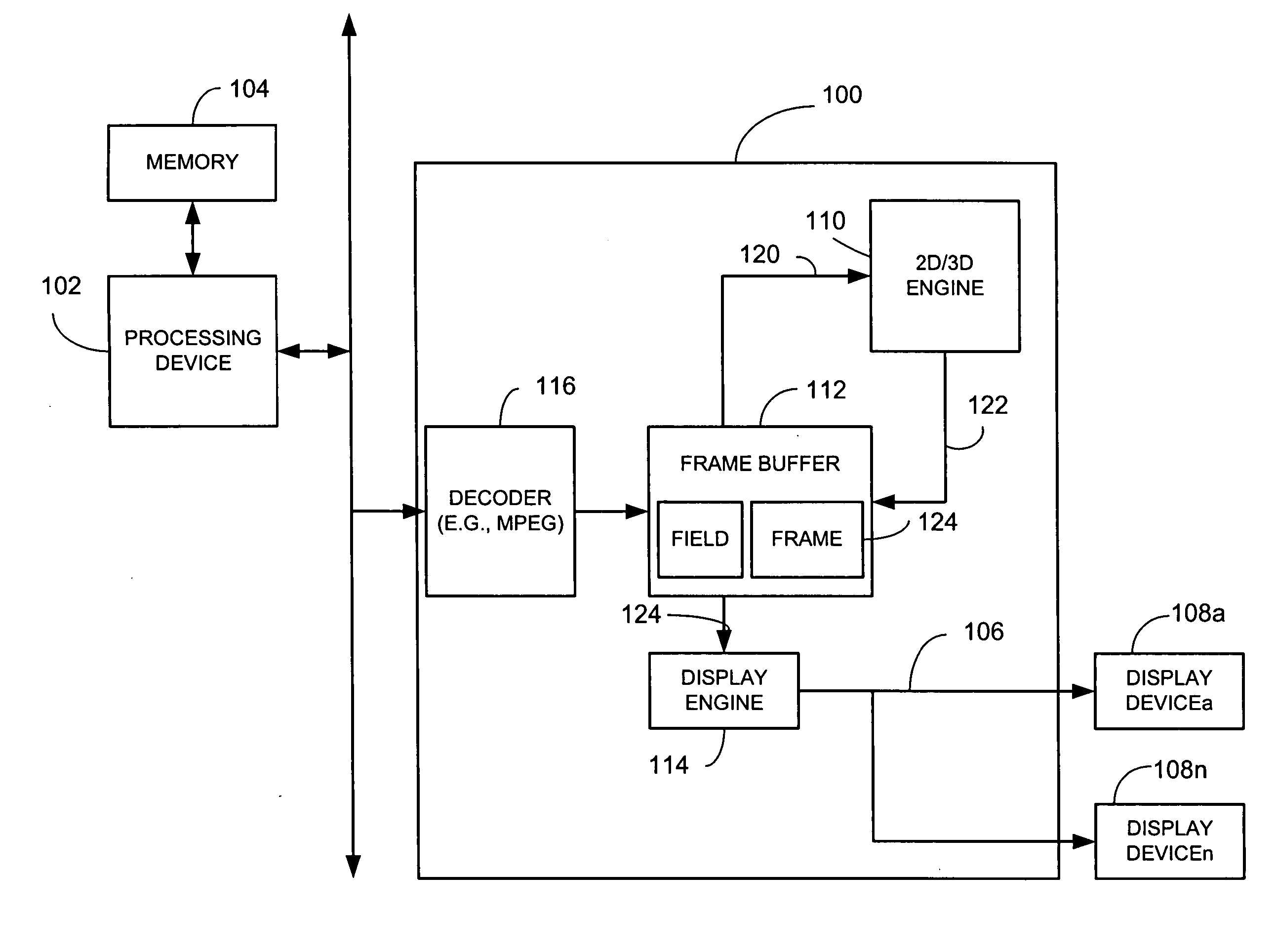
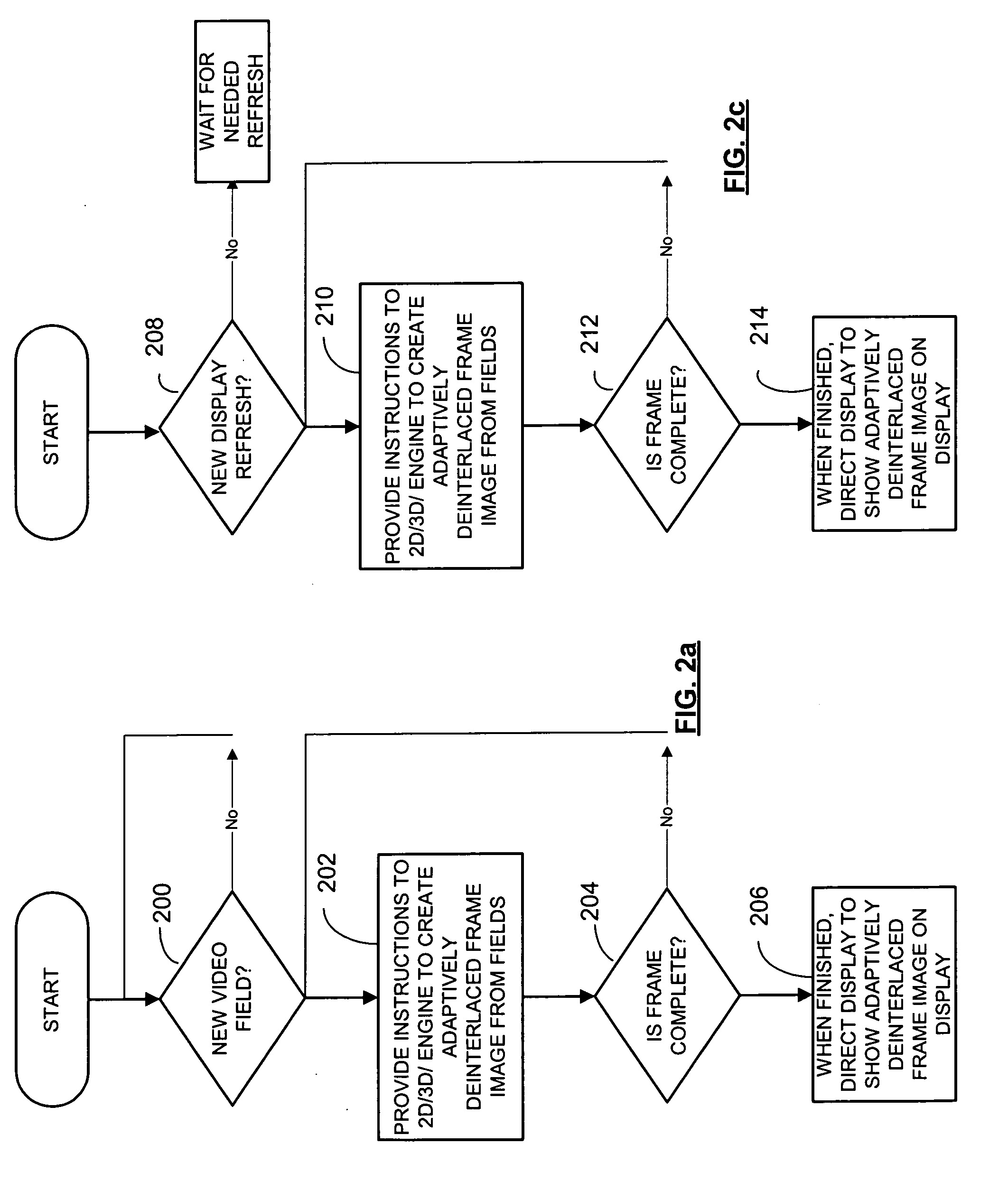
[0028] A method for deinterlacing interlaced video using a graphics processor includes receiving at least one instruction for a 2D / 3D engine, such as a rendering engine, drawing engine or other suitable structure that receives or reads in image data, renders image data and writes out image data, to facilitate creation of an adaptively deinterlaced frame image from at least a first interlaced field. The method also includes performing, by the 2D / 3D engine, at least a portion of adaptive deinterlacing based on at least the first interlaced field, in response to the at least one instruction to produce at least a portion of the adaptively deinterlaced frame image. Once the information is deinterlaced, the method includes retrieving, by a graphics processor display engine, the stored adaptively deinterlaced frame image generated by the 2D / 3D engine, for display on one or more display devices. The method also includes issuing 2D / 3D instructions to the 2D / 3D engine to carry out deinterlaci...


PUM


Abstract

A method for deinterlacing interlaced video using a graphics processor includes receiving at least one instruction for a 2D / 3D engine to facilitate creation of an adaptively deinterlaced frame image from at least a first interlaced field. The method also includes performing, by the 2D / 3D engine, at least a portion of adaptive deinterlacing based on at least the first interlaced field, in response to the at least one instruction to produce at least a portion of the adaptively deinterlaced frame image. Once the information is deinterlaced, the method includes retrieving, by a graphics processor display engine, the stored adaptively deinterlaced frame image generated by the 2D / 3D engine, for display on one or more display devices. The method also includes issuing 2D / 3D instructions to the 2D / 3D engine to carry out deinterlacing of lines of video data from interlaced fields. This may be done, for example, by another processing device, such as a host CPU, or any other suitable processing device.

Description

RELATED CO-PENDING APPLICATION [0001] This is a related application to an application entitled, “Method and Apparatus for Deinterlacing Video,” having Ser. No. 09 / 539,572 filed on Mar. 31, 2000 and owned by instant assignee and incorporated by reference.FIELD OF THE INVENTION [0002] The invention relates generally to methods and devices for de-interlacing video for display on a progressive display and more particularly to methods and apparatus for de-interlacing interlaced content using a 2D / 3D engine. BACKGROUND OF THE INVENTION [0003] Progressive display devices display all lines of an image every refresh. In contrast, interlaced display devices, such as NTSC and PAL television displays, typically display images using even and odd line interlacing. To display interlaced video on a progressive display, video rendering systems have to generate pixel data for scan lines that are not received in time for the next frame update. This process is called de-interlacing. When such interlace...

Claims


Application Information

Patent Timeline
IPC IPC(8): H04N5/44H04N7/01H04N11/20
CPCH04N7/012
Inventor SWAN, PHILIP L.CALLWAY, EDWARD G.
Owner ATL INT
Learn More