
Selectively controllable heads-up display system

a display system and control technology, applied in the field of electronic display systems and control systems, can solve the problems of more distraction opportunities, difficult for surgeons to focus on their or their conduct, and distract surgeons from immediate tasks

Inactive Publication Date: 2005-09-22
LEMELSON JEROME H +1
View PDF99 Cites 355 Cited by
  • Summary
  • Abstract
  • Description
  • Claims
  • Application Information

AI Technical Summary

Benefits of technology

[0021] It is another object of the invention to provide an improved head-mounted display that allows the user to view both the subject and selected data.
[0036] The above and other objects are also achieved in an user-controllable heads-up system for presenting medical data to a physician. The system includes a command control computer for receiving inputs defining medical data and for controlling the display of that data on a head's-up display screen in the normal field of view of the physician. The heads-up display provides the physician with a “user interface” including menus and associated operations that can be selected with an eye-tracking cursor. The system also includes a microphone and speaker so that a physician can communicate with other personnel and computers both locally and remote from the cite. The command computer includes a speech recognition processor to respond to spoken commands of the physician. The command computer also communicates with and receives a wide array of data from other computers networked therewith. The physician can select the specific data to be displayed on the screen. In addition, the physician can, with the eye-tracking cursor, control various medical imaging devices.

Problems solved by technology

Although the additional information is necessary and important, monitoring such information often diverts the surgeon from the immediate task at hand.
However, as more tools and sources of data become available to surgeons for use during operations, more opportunities for distraction arise.
It is difficult for a surgeon to focus on his or her conduct during a surgical procedure while also continually shifting focus away from the patient to other monitors or indicators.
As explained in greater detail below, prior attempts in the medical field to fulfill that need have been unsatisfactory.
However, Schoolman I and Schoolman II do not use a “see through” display that allows the surgeon to monitor both the environment around him and the video image.
However, as explained in the associated literature, the “tracking” requirements made the research effort quite complicated, and the results appeared less than satisfactory.
Moreover, such a teaching system is not applicable to the real-world environment of a surgeon, where the patient is not moved (and “tracking” is unnecessary), and where the surgeon needs or desires other information to be made readily available for viewing.
However, the article does not disclose the use of see-through displays providing a surgeon with the ability to select and display additional forms of data, or to superimpose data over a real-life view of the patient or surgical site.
However, as above, the user can not select additional or alternative forms of data or different images to be superimposed over the primary image on the head-mounted display.
Thus, few head-mounted displays have been developed for the medical industry, and all those described above have had limited purpose and utility.
Notwithstanding the large number of articles and patents issued in the area of heads-up or head-mounted displays, there has been no such display that is designed for the special needs of individuals performing detailed but critical tasks on relatively stationary subjects.

Method used


Image

  • Selectively controllable heads-up display system
  • Selectively controllable heads-up display system
  • Selectively controllable heads-up display system

Examples


Embodiment Construction

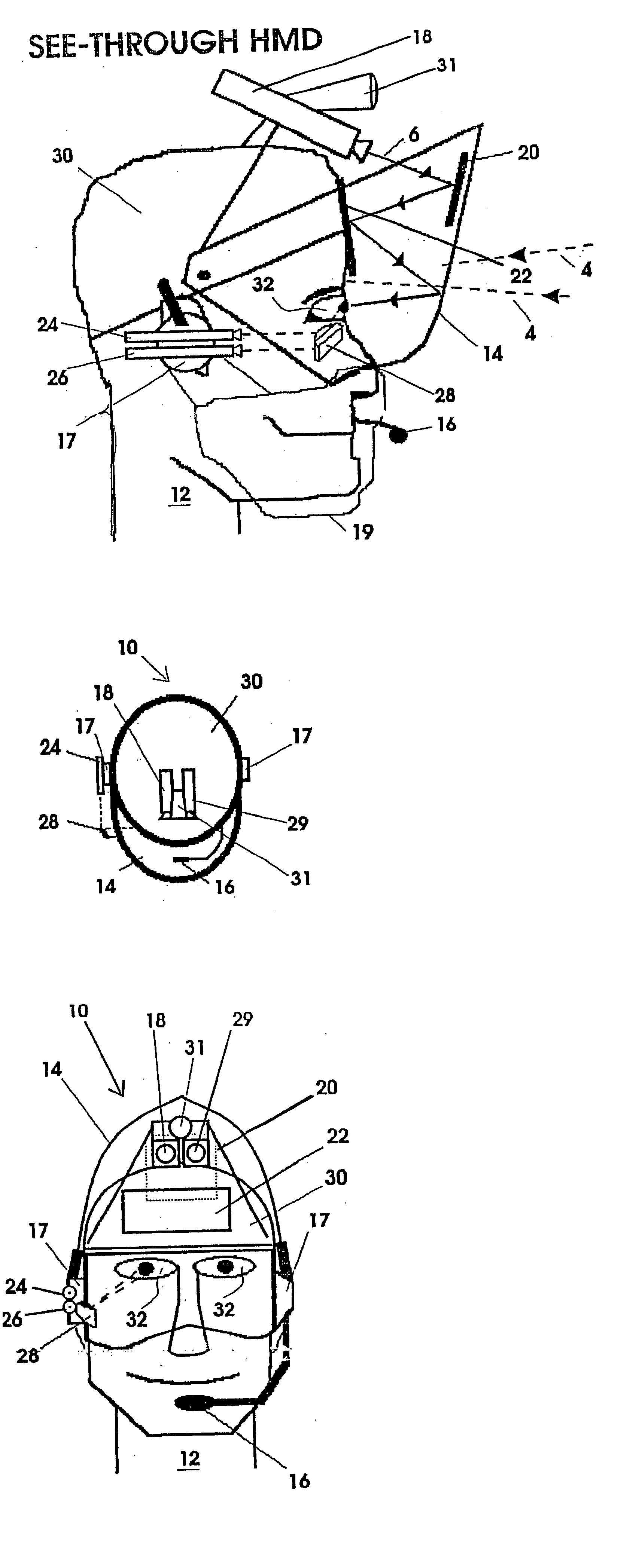
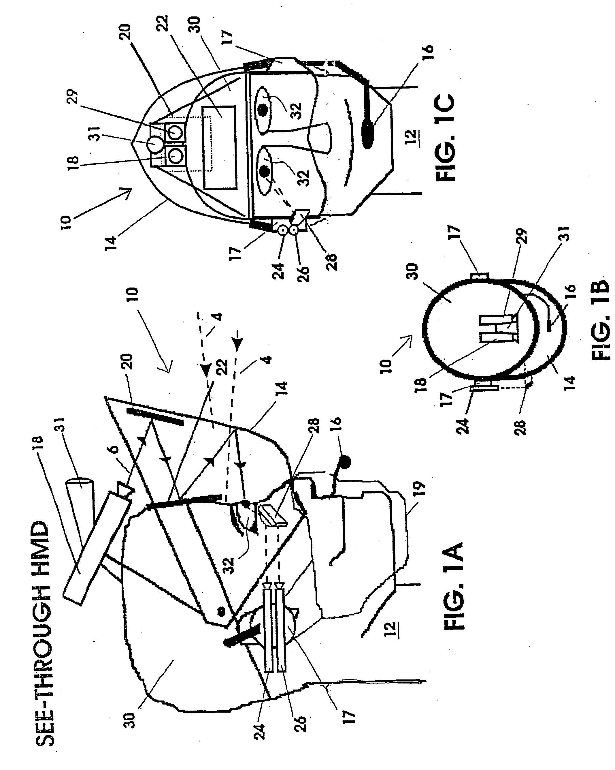
[0060] Shown in FIGS. 1A, 1B and 1C are three views of a head-mounted, selectable, display system 10. In the preferred embodiment shown in the Figures, the display system 10 is worn by a surgeon 12 performing an operation. However, the system is easily programmed for use by any individual performing detailed procedures in which it is advantageous to see the normal field of view, while also having access to and seeing in that field of view a variety of forms of data relating to the procedure. Thus, it is envisioned that a display in accordance with this invention will have many applications, but is primarily intended for procedures where detailed work is performed on relatively stationary objects. Accordingly, while the description below refers repeatedly to the user as a “surgeon”, it should be understood that the other users are included in the scope of the invention.

[0061] For convenience, the phrases “head-mounted display,”“heads-up display” and “HUD” are used interchangeably th...


PUM


Abstract

Systems and methods are disclosed for displaying data on a head's-up display screen. Multiple forms of data can be selectively displayed on a semi-transparent screen mounted in the user's normal field of view. The screen can either be mounted on the user's head, or mounted on a moveable implement and positioned in front of the user. A user interface is displayed on the screen including a moveable cursor and a menu of computer control icons. An eye-tracking system is mounted proximate the user and is employed to control movement of the cursor. By moving and focusing his or her eyes on a specific icon, the user controls the cursor to move to select the icon. When an icon is selected, a command computer is controlled to acquire and display data on the screen. The data is typically superimposed over the user's normal field of view.

Description

FIELD OF THE INVENTION [0001] The inventions relate to electronic display systems and control systems therefor. More particularly the inventions relate to selectively operable heads-up display systems for presenting information and / or image(s) to the user. In its preferred form, the heads-up display is configured for use by medical technicians or personnel, such as surgeons performing an operation. BACKGROUND OF THE INVENTION [0002] A heads-up display is generally defined as an electronically generated display containing information or data that is superimposed on an observer's normal field of view. As explained in greater detail below, heads-up display (“HUD”) systems have been used in various applications. One such application is for use by pilots of aircraft. In the typical aircraft HUD system, a semi-transparent display screen is located generally in front of the eyes of the pilot (i.e. a screen mounted on the pilot's head or helmet, or in the view of the aircraft windshield). S...

Claims


Application Information

Patent Timeline
Patent Type & Authority Applications(United States)
IPC IPC(8): A61B3/113G02B27/00G02B27/01
CPCA61B1/00048A61B1/0005A61B3/113G02B2027/0187G02B27/017G02B2027/0138A61B5/7445H04N7/147G16H40/63G16H20/40
Inventor LEMELSON, JEROME H.HIETT, JOHN H.
Owner LEMELSON JEROME H
Learn More