
Battery charger with automatic customer notification system

Inactive Publication Date: 2005-09-22
MIDTRONICS
View PDF99 Cites 38 Cited by
  • Summary
  • Abstract
  • Description
  • Claims
  • Application Information

AI Technical Summary

Problems solved by technology

This may be inconvenient when the charger user has to carry out other tasks at locations that are remote from the charger.

Method used


Image

  • Battery charger with automatic customer notification system
  • Battery charger with automatic customer notification system
  • Battery charger with automatic customer notification system

Examples


Embodiment Construction

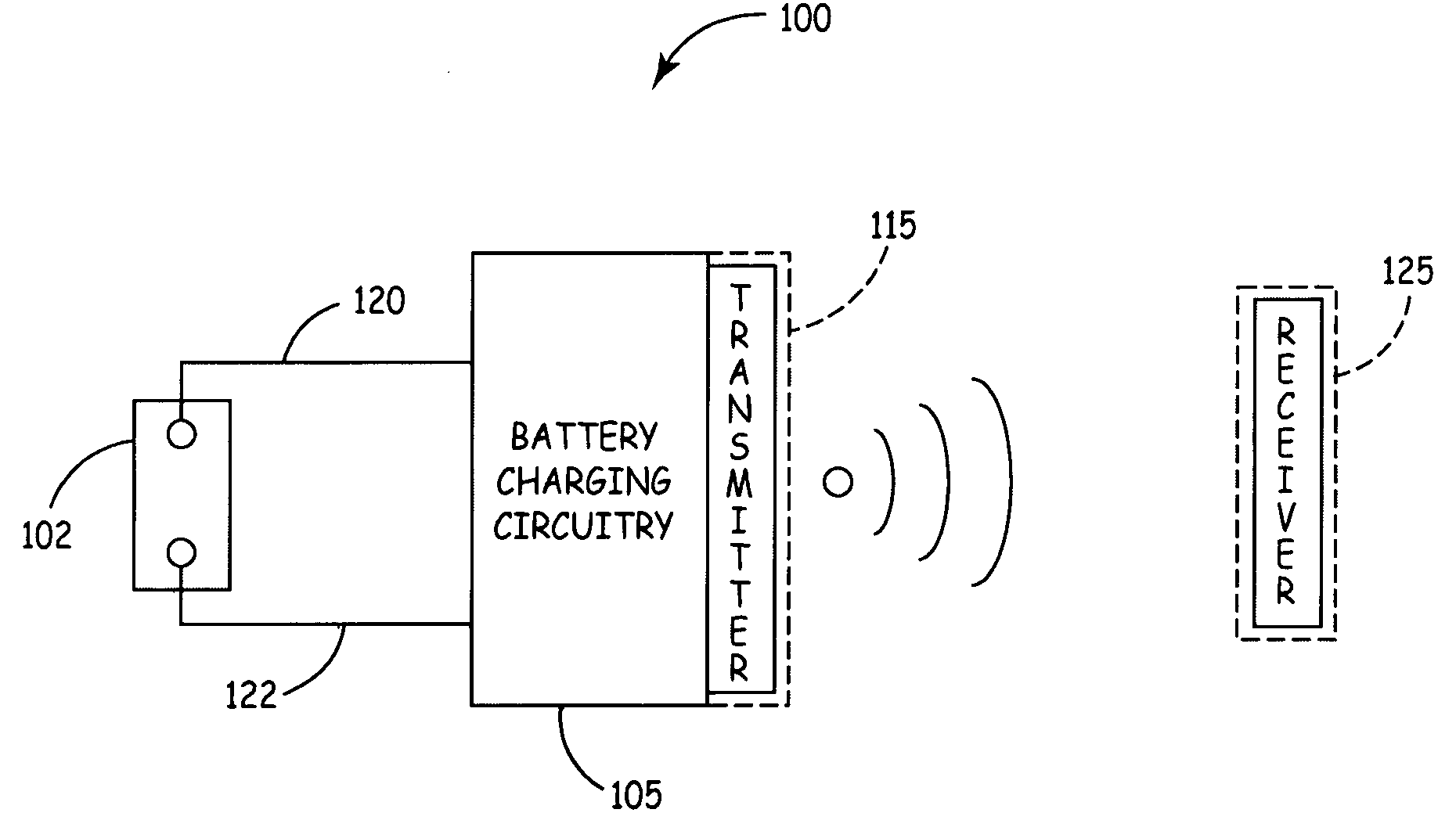
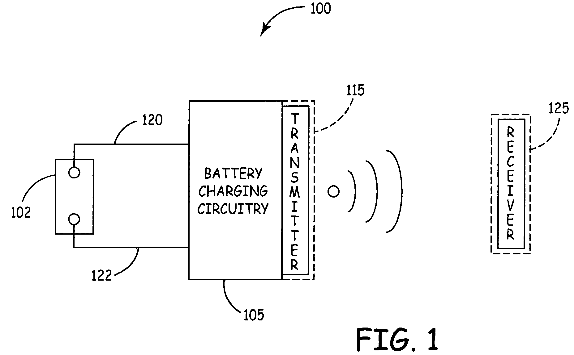
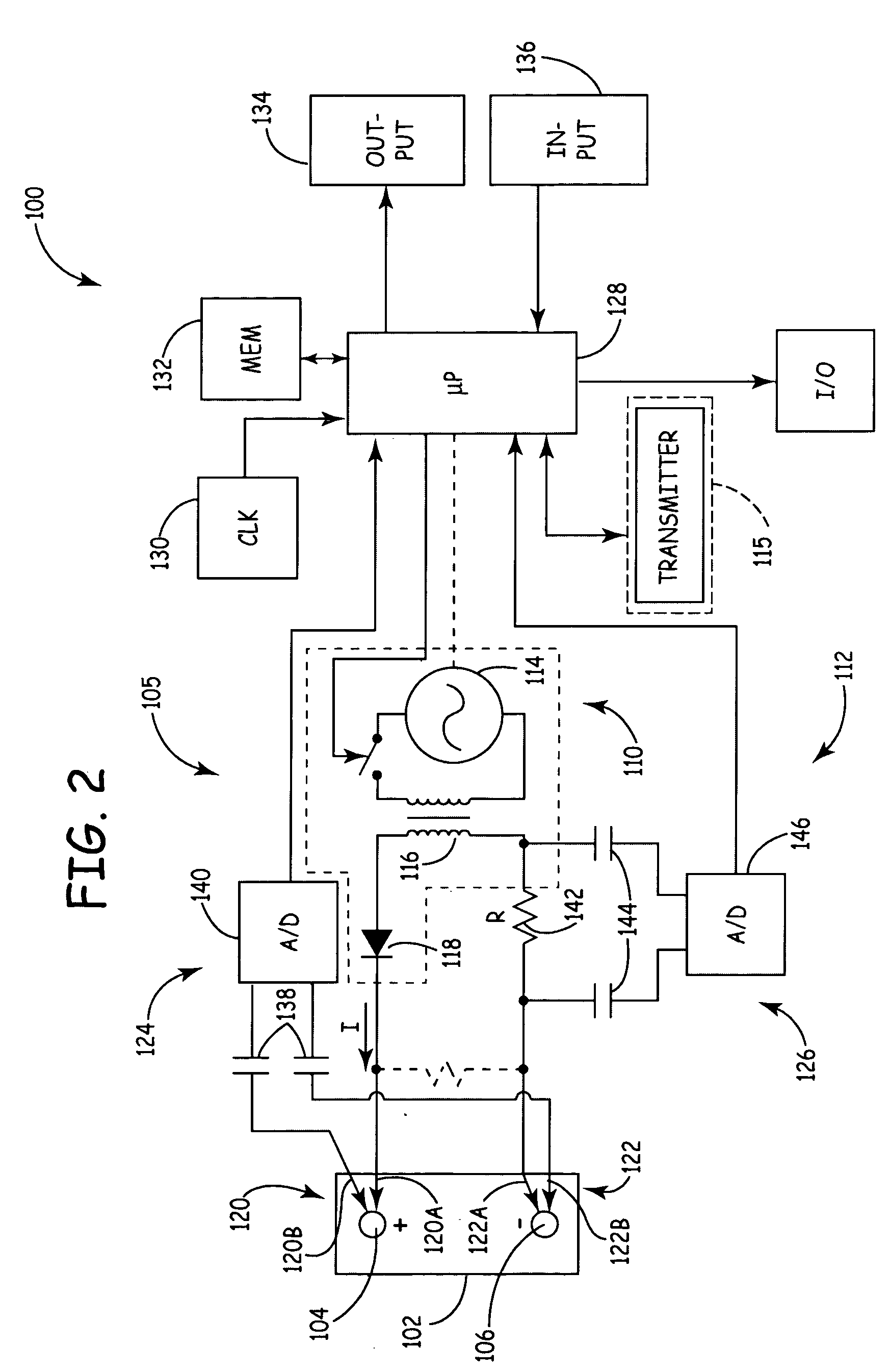
[0009]FIG. 1 is a simplified block diagram illustrating an example battery charger 100 that includes a customer / user notification system in accordance with an embodiment of the present invention. Battery charger 100 includes battery charging circuitry 105, which can couple to storage battery 102 through electrical connectors 120 and 122 to charge battery 102. As can be seen in FIG. 1, battery charger 100 also includes communication circuitry 115, coupled to charging circuitry 105, which includes a transmitter / transceiver. Communication circuitry 115 is capable of transmitting signals to an external device 125, which is located within the coverage area of communication circuitry 115. External device 125 includes a receiver. Charging circuitry 105, which is described in detail further below, provides a charge status code to communication circuitry 115 as soon as battery 102 is charged, for example. Upon receipt of the charge status code from charging circuitry 105, communication circu...


PUM


Abstract

A battery charger with an automatic customer notification system is provided. The battery charger includes battery charging circuitry which is configured to couple to a battery, and to provide a charging signal to the battery. The battery charger also includes communication circuitry, coupled to the charging circuitry, that is configured to transmit a signal to an external device upon receipt of a charge status code form the battery charging circuitry.

Description

BACKGROUND OF THE INVENTION [0001] The present invention relates to rechargeable storage batteries. More specifically, the present invention relates to charging such storage batteries. [0002] Chemical batteries which create electricity from chemical reactions have been known for many years. Such batteries are becoming increasingly important and have found uses throughout industry. These uses include automobiles, UPS systems, etc. [0003] One advantage of chemical batteries, such as lead acid storage batteries, is that they can be charged and the chemical process reversed by forcing electricity through the battery. Charging systems are widely known in the art and are widely available in the consumer market. Some charging systems include both battery charging and battery testing circuitry and are therefore capable of determining the battery condition before, during and after battery charging. [0004] Various examples of battery chargers and testers are described in U.S. Pat. No. 3,873,9...

Claims


Application Information

Patent Timeline
IPC IPC(8): H02J7/00
CPCH02J7/0047H02J7/0049
Inventor SMITH, CLARK E.BERTNESS, KEVIN I.
Owner MIDTRONICS
Learn More