
Display screen burn prevention method

a technology for display screens and burn prevention, applied in the field of prevention of display screen burn, can solve the problems of screen burn, inability to completely prevent screen burn, and exposure to degradation of phosphors, and achieve the effect of effectively preventing display screen burns and burns

Inactive Publication Date: 2005-09-15
PIONEER CORP
View PDF10 Cites 69 Cited by
  • Summary
  • Abstract
  • Description
  • Claims
  • Application Information

AI Technical Summary

Benefits of technology

[0009] An object of the present invention is to provide a display screen burn preventing method which can effectively prevent display screen burns.
[0010] According to a first aspect of the present invention, there is provided an improved method for preventing display screen burn of a display device. The display device displays images corresponding to an input image signal. When the display device is operated in a certain mode, the display screen burn prevention method applies a unique display position moving process which gradually moves the display position of the image in an oblique direction in the display screen.

Problems solved by technology

Displays such as CRTs (Cathode Ray Tubes) and plasma display panels, which make use of the photoemission phenomenon which accompanies the excitement of phosphors, are subjected to degradation of the phosphors and so-called screen burn when a still image is continuously displayed for a long period of time.
However, with these actions for preventing screen burn, the following problems occur if “tables” which contain ruled lines extending in the horizontal direction and vertical direction of the screen are displayed as the still image.
Therefore, the screen burn cannot completely be prevented by these screen burn preventing actions.

Method used


Image

  • Display screen burn prevention method
  • Display screen burn prevention method
  • Display screen burn prevention method

Examples


Embodiment Construction

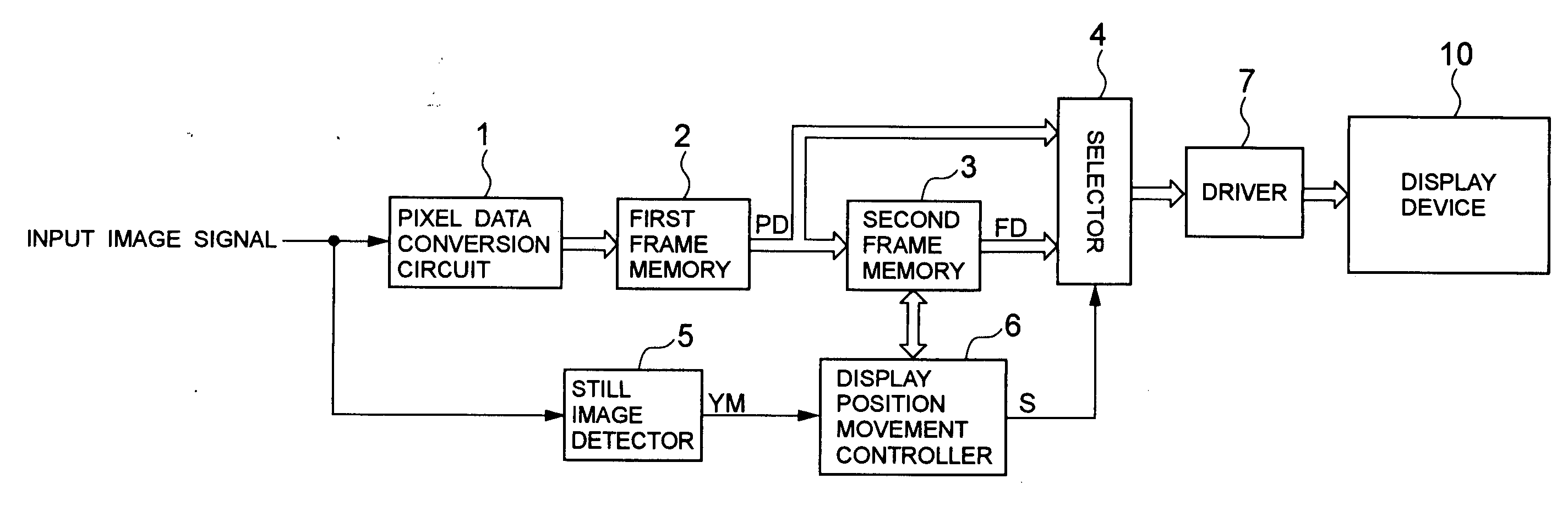
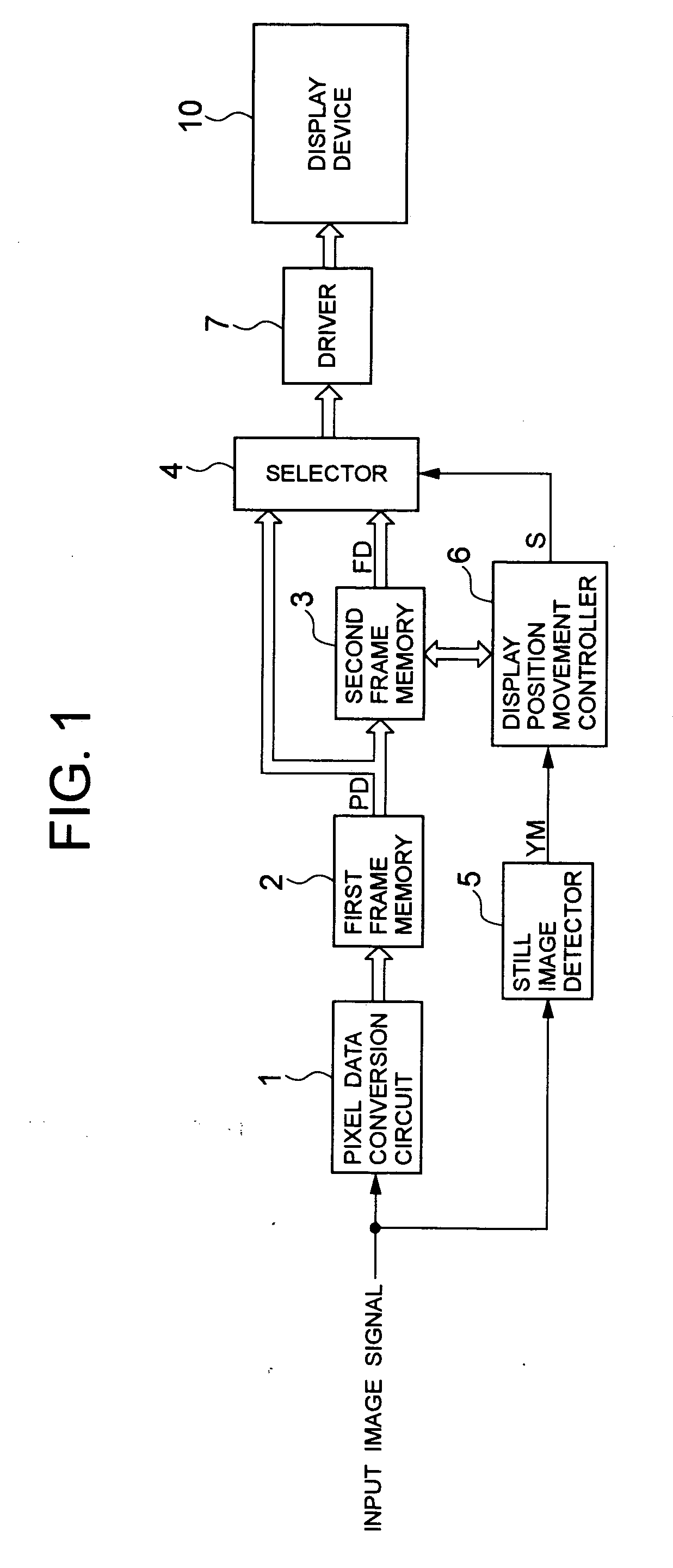
[0024] Referring to FIG. 1, a structure of a display device 10 with a display screen burn prevention function will be described.

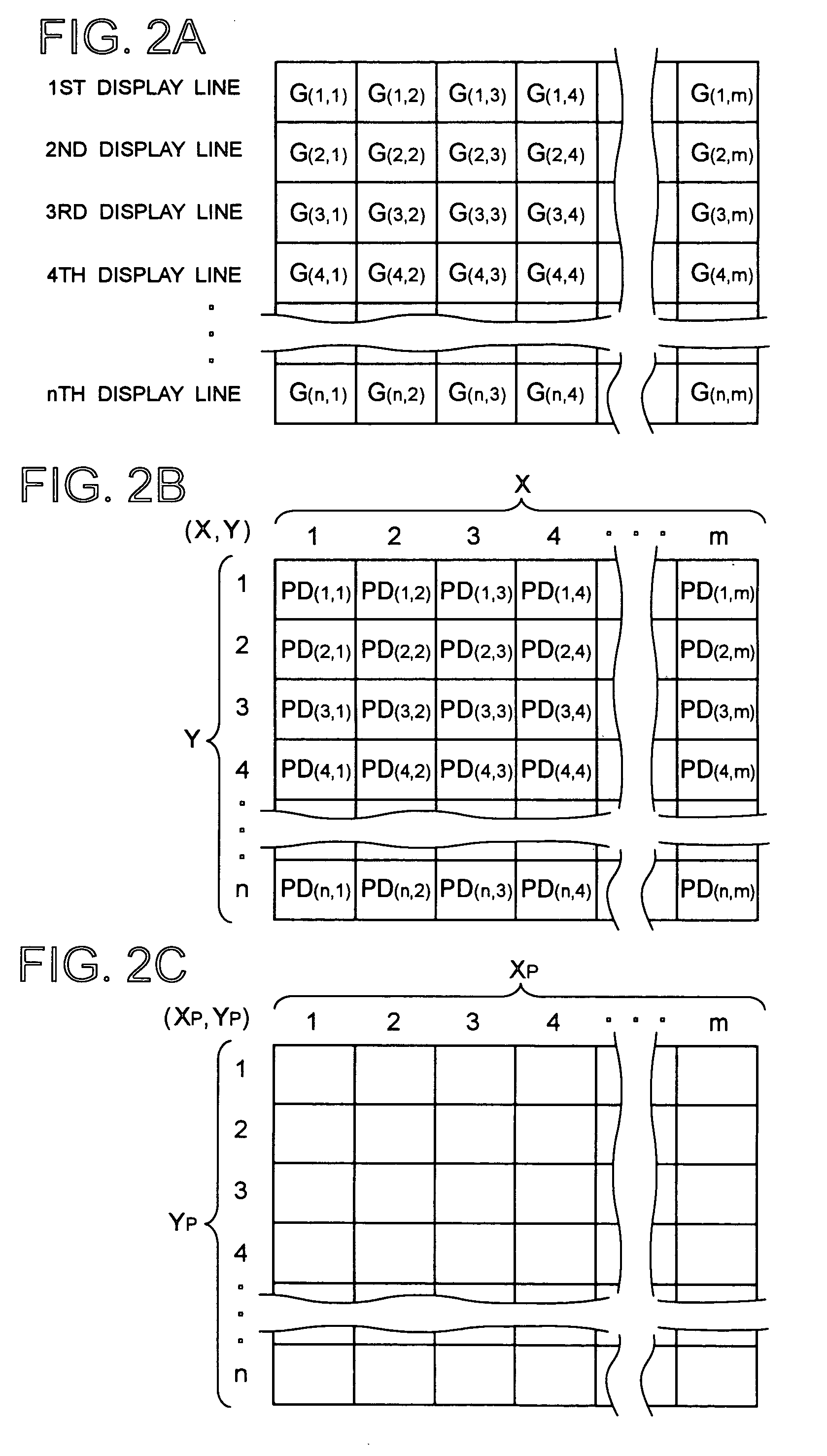
[0025] In FIG. 1, a display device 10 is a CRT (Cathode Ray Tube) or a plasma display panel or the like, and pixels G(1,1)-G(n,m) are arranged as shown in FIG. 2A in this screen (n rows×m columns). Each of the pixels G(1,1)-G(n,m) is actually a combination of three pixels. The three pixels are a red pixel GR which emits red light, a green pixel GG which emits green light, and a blue pixel GB which emits blue light. A driver 7 is connected to the display device 10.

[0026] An input image signal is introduced to a pixel data converter circuit 1 and a still image detection circuit 5. The pixel data converter circuit 1 is connected to a first frame memory 2. The first frame memory 2 is connected to a second frame memory 3 and a selector 4. The selector 4 is connected to the display device driver 7. The still image detection circuit 5 is connected to a display p...


PUM


Abstract

The display position of an image on a display screen is gradually moved in an oblique direction in a specified display mode. Accordingly, display screen burn is prevented.

Description

BACKGROUND OF THE INVENTION [0001] 1. Field of the Invention [0002] The present invention relates to a method for preventing display screen burn in image display devices. [0003] 2. Description of the Related Art [0004] Displays such as CRTs (Cathode Ray Tubes) and plasma display panels, which make use of the photoemission phenomenon which accompanies the excitement of phosphors, are subjected to degradation of the phosphors and so-called screen burn when a still image is continuously displayed for a long period of time. [0005] In order to prevent such screen burn, a screen burn prevention method is proposed in Japanese Patent Kokai (Laid-open Application) No. 2000-227775. This method forces gradual movement of the display position of a displayed object on a screen over time. [0006] With this screen burn prevention method, first the object displayed in a still image is gradually moved horizontally to the right in one dot increments for five dots. Next, the object displayed is moved v...

Claims


Application Information

Patent Timeline
Patent Type & Authority Applications(United States)
IPC IPC(8): G06F17/00H04N5/66G09G1/00G09G3/20G09G3/291G09G5/00
CPCG09G3/007G09G3/28G09G2340/0464G09G2320/046G09G2320/0219
Inventor ENOKI, KENICHINAGANUMA, HIDEOOHKITA, TAKASHIKAMADA, NORIYUKI
Owner PIONEER CORP
Learn More