Wheelchair wheel immobilizer

a technology of immobilizer and wheel, which is applied in the direction of hand cart accessories, medical transportation, ambulance service, etc., can solve the problems of difficulty in preventing the difficulty of adjusting the position, so as to prevent the rotation of the wheel

Inactive Publication Date: 2005-09-15
LAWRENCE NELSON
View PDF41 Cites 5 Cited by
  • Summary
  • Abstract
  • Description
  • Claims
  • Application Information

AI Technical Summary

Benefits of technology

[0008] In one aspect, the present invention provides a wheel immobilizer for substantially preventing rotation of a wheelchair wheel or tire about a central axis thereof. The wheel immobilizer may comprise a pivoting wheel stop carrying a detent and a rotating cam having a receiver in which the detent seats when the wheel immobilizer is in an unlocked position (with the wheel stop held at a spaced distance from the wheel) to allow rotation thereof. A lever is operably connected to the cam, whereby actuating the lever in a forward or backward direction rotates the cam and unseats the detent from the receiver, urging a wheel-contacting surface of the wheel stop into locking contact with the wheel. The cam may be substantially circular in shape.
[0012] The second wheel immobilizer includes a second pivoting wheel stop which is operably connected to the first wheel stop by a substantially continuously flexible linkage, whereby actuating the lever to urge the first wheel stop wheel-contacting surface into locking contact with the first wheel or tire also urges a wheel-contacting surface of the second wheel stop into contact with the second wheel or tire of the wheelchair. In this fashion, locking of both wheels of a wheelchair may be accomplished by actuating a single lever from a single side of the wheelchair, which provides a significant advantage to a user suffering from greater weakness in a particular hemisphere of the body, such as is common for stroke victims. The substantially continuously flexible linkage may comprise a flexible member such as a wire or cable having a first end operably connected to the first wheel stop and a second end operably connected to the second wheel stop.

Problems solved by technology

Further, such push-pull locks often have relatively short operating levers which, while avoiding inconvenience to the user, may require a level of strength which certain handicapped individuals may simply not possess.
Simply elongating the operating lever to improve the leverage thereof may not be convenient, as an elongated lever may be obtrusive to the user.
Multiple linkages and wheel-contacting surfaces add complexity and weight to a wheel lock, increasing both the cost of manufacture (and the subsequent cost to the user) and the likelihood of component failure necessitating repair.

Method used


Image

  • Wheelchair wheel immobilizer
  • Wheelchair wheel immobilizer
  • Wheelchair wheel immobilizer

Examples


Embodiment Construction

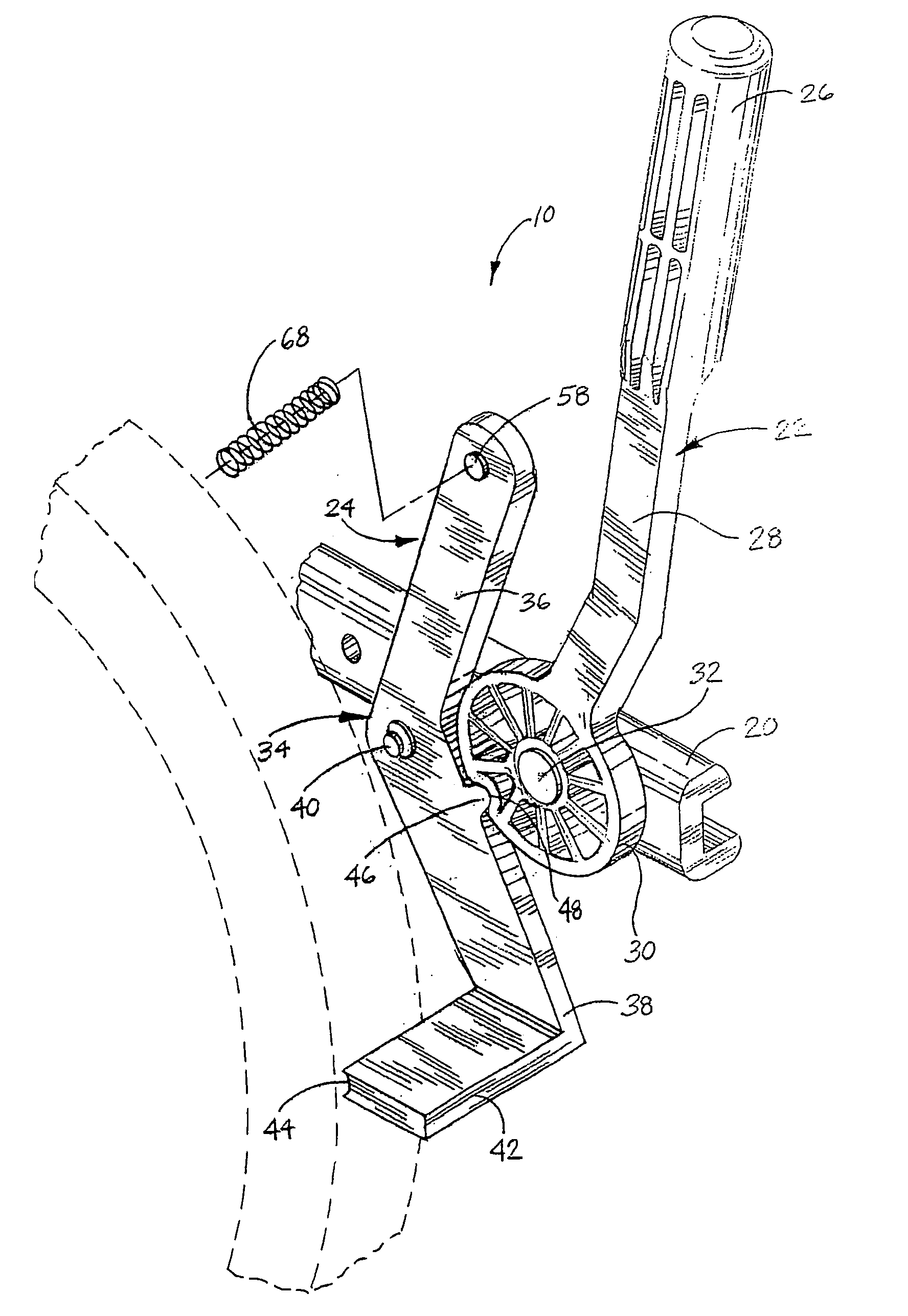
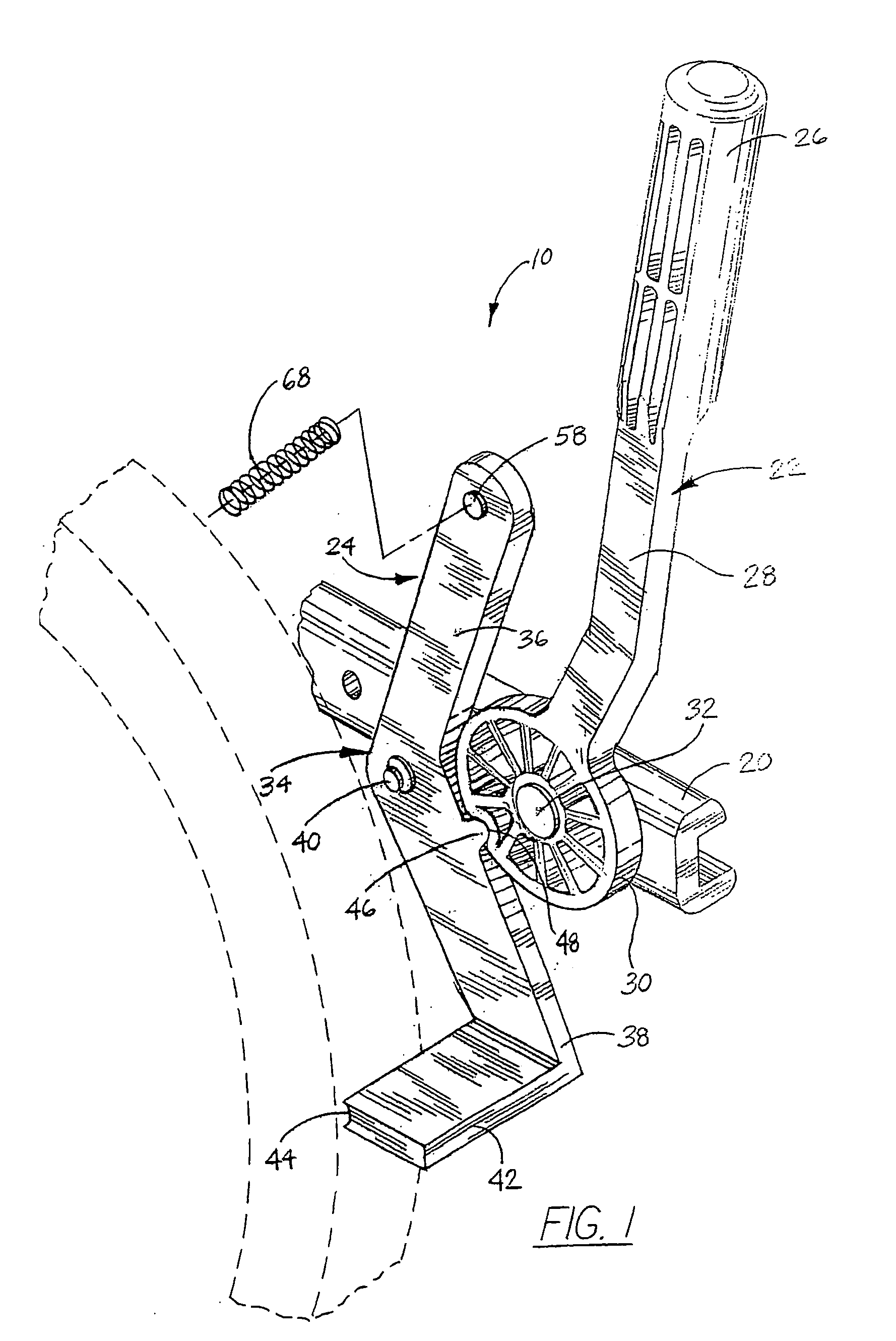
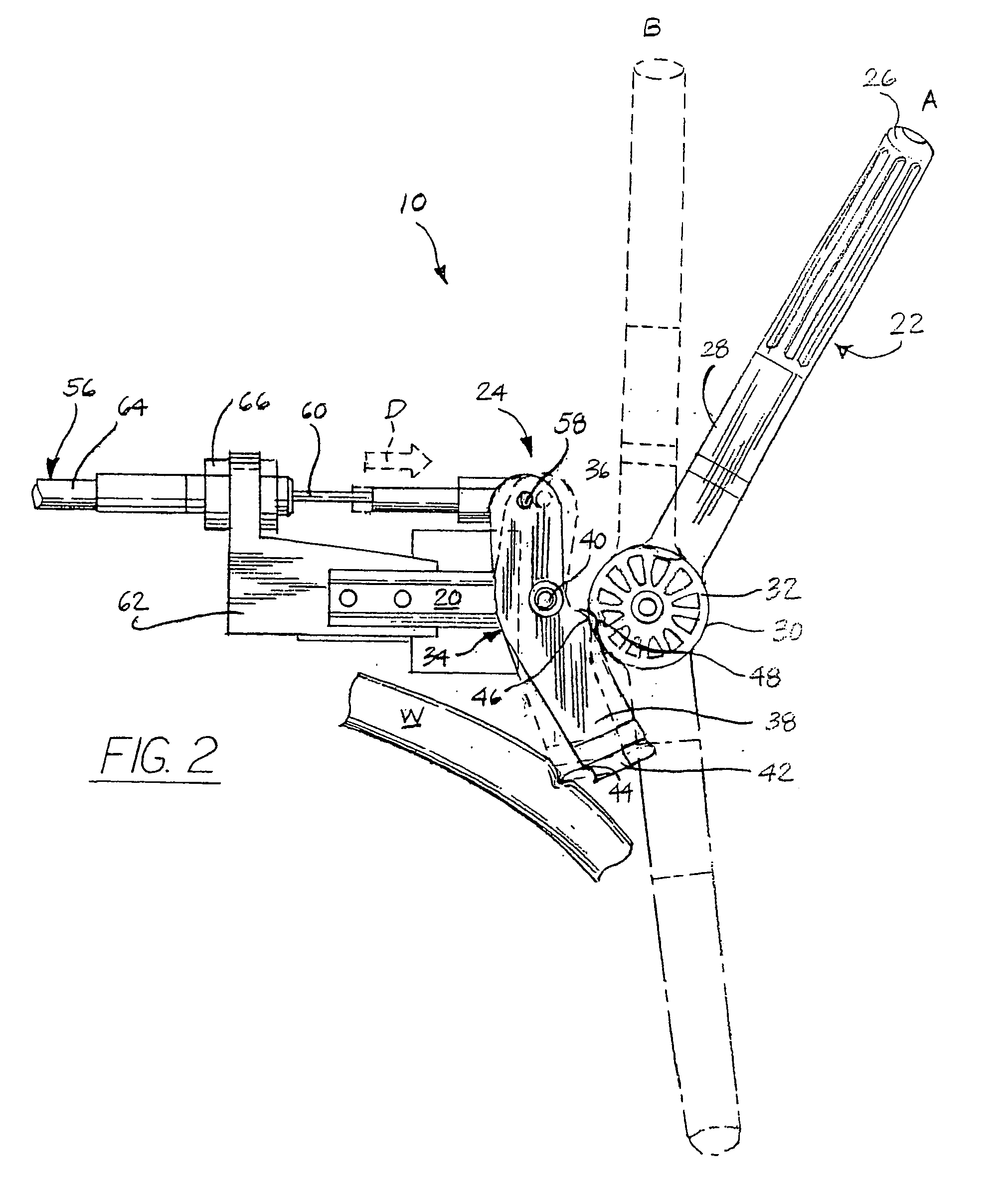
[0021] Referring to FIG. 1, in the depicted embodiment the wheel immobilizer 10 of the present invention comprises a mounting block 20 of a type well known in the art, an elongated lever 22, and a pivoting wheel stop 24. Mounting block 20 is adapted for connecting to an element of a wheelchair such as the frame (not shown). It will be appreciated by those of skill in the art that mounting block 20 may be fabricated to any desired configuration for mounting to a wheelchair in accordance with the manufacture of the wheelchair frame, such as by threaded nuts and bolts, clamps, and the like. Thus, the wheel immobilizer 10 of the present invention may be incorporated into the wheelchair during manufacture, or may be retrofitted to any existing manufacture of wheelchair. However, it should also be appreciated that the components of wheel immobilizer 10 could be directly attached to a wheelchair (not shown), such as by bolting to, e.g., the frame.

[0022] Lever 22 includes a gripping end 26...


PUM


Abstract

A wheel immobilizer for substantially preventing rotation of a wheelchair wheel or tire about a central axis thereof is provided comprising a pivoting wheel stop carrying a detent and a rotating cam having a receiver. The detent seats in the receiver when the wheel immobilizer is in an unlocked position (with the wheel stop held at a spaced distance from the wheel) to allow rotation thereof. A lever is operably connected to the cam, whereby actuating the lever rotates the cam and unseats the detent from the receiver, urging a wheel-contacting surface of the wheel stop into locking contact with the wheel. In another aspect, a wheel locking assembly is provided comprising paired wheel immobilizers as described which may be operated independently. In still another aspect, a wheel locking assembly is provided comprising a first and second wheel immobilizer, wherein the first and second wheel immobilizers are operably linked by a flexible linkage.

Description

[0001] This application claims the benefit of priority in U.S. Provisional Patent Application Ser. No. 60 / 396,918, filed Jul. 17, 2002.FIELD OF THE INVENTION [0002] This invention relates generally to the field of wheel locking mechanisms for wheelchairs. In particular, the present invention relates to a push-pull wheelchair lock whereby a wheel of a wheelchair may be immobilized by either pulling up or pushing down on the lock. The wheelchair wheel lock of the present invention is adapted for use by individuals who may be unable to operate conventional push-pull locks, providing improved wheel locking power with use of minimal force. BACKGROUND OF THE INVENTION [0003] It is known to provide wheelchairs with mechanisms for locking the wheels thereof, preventing the wheelchairs from traveling except at the urging of the user or an assistant. One design of wheelchair lock incorporates a “push-pull” mechanism comprising a lever operably connected to a wheel strike, whereby the user may...

Claims


Application Information

Patent Timeline
Patent Type & Authority Applications(United States)
IPC IPC(8): B62B5/04
CPCA61G5/1018B62B5/0457A61G5/1035A61G5/101B62B5/0485
Inventor TANKSLEY, KEITH A.DONALDSON, BRUCE S.
Owner LAWRENCE NELSON
Why Eureka
Try Eureka