
Method for detecting link partner state during auto negotiation and switching local state to establish link

a technology of auto negotiation and link partner state, applied in the field of network interface connection devices, can solve problems such as inability to communicate, and achieve the effect of facilitating the exchange of configuration information

Active Publication Date: 2005-09-08
III HLDG 2
View PDF5 Cites 17 Cited by
  • Summary
  • Abstract
  • Description
  • Claims
  • Application Information

AI Technical Summary

Benefits of technology

[0006] The present invention disclosed and claimed herein, in one aspect thereof, comprises a method for allowing a host network node to establish a compatible communication link with a link partner network node disposed on the opposite end of a physical communication link from the host network node. The host node monitors data traffic received from the link partner network node. The host node then determines from the monitored data traffic from the link partner network node if the link partner network node is requesting configuration information from the host network node. If a request for configuration information is received from a link partn...

Problems solved by technology

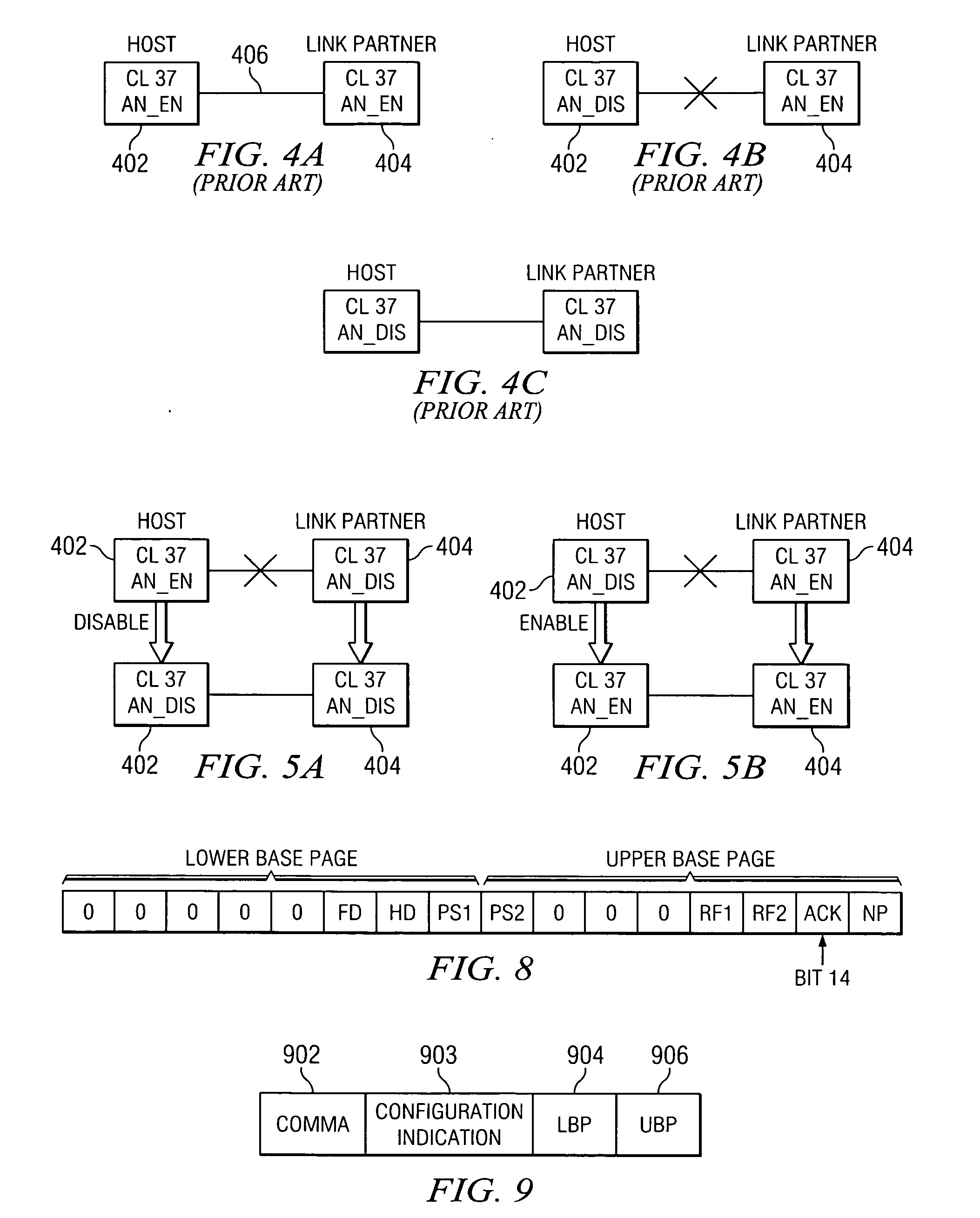
However, if an attempt is made to interface an unknown device with the switch wherein the unknown device has the Auto Negotiation enabled, then communication is not possible due to the fact that the fiber interface on the switch or local side operates in accordance with Clause 37 of the standard.

Method used


Image

  • Method for detecting link partner state during auto negotiation and switching local state to establish link
  • Method for detecting link partner state during auto negotiation and switching local state to establish link
  • Method for detecting link partner state during auto negotiation and switching local state to establish link

Examples


Embodiment Construction

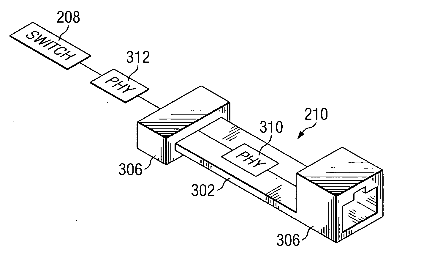
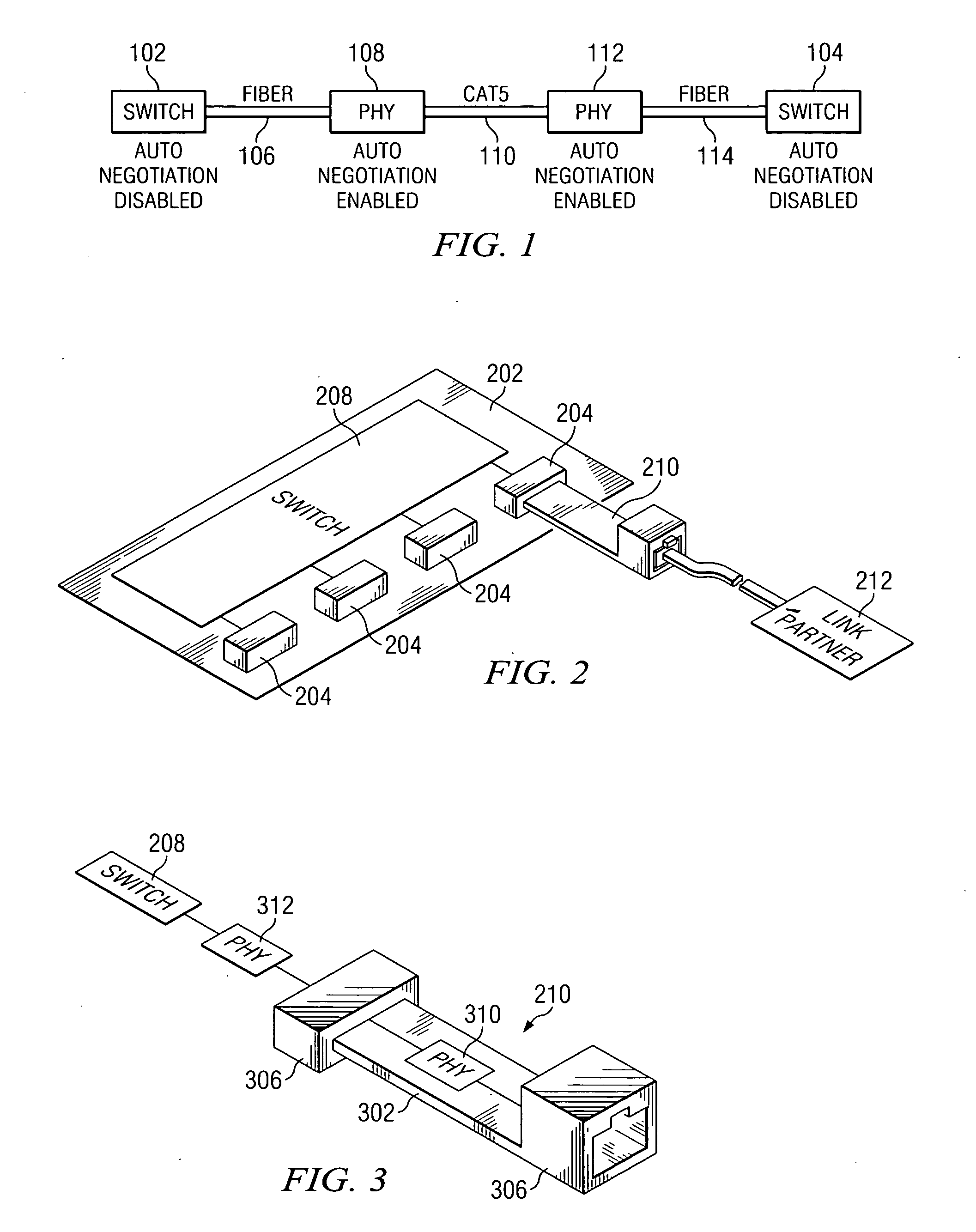
[0017] Referring now to FIG. 1, there is diagrammatic view of an interconnection between two ends of network. In this configuration, there is provided a switch 102 on a first end and a switch 104 on a second end. Initially, these switches 102 and 104 are configured to work with a fiber connection wherein the network interface will be a serial interface and the protocol is facilitated with a protocol termed “SerDes” which is an acronym for serializer / deserializer. In the configuration illustrated in FIG. 1, the switch 102 is connected through a fiber connection 106 to an intermediate interconnection device which has associated therewith a physical layer, PHY, 108. The switch 102 also has a PHY associated therewith, which is internal thereto in order to allow it to communicate with the PHY 108. The PHY 108 is operable to provide the physical interface to the switch 102 through the fiber 106 in a SerDes format, such that data can be received from the switch 102 serving as the link part...


PUM


Abstract

Method for detecting link partner state during Auto Negotiation then switching local state to establish link A method is disclosed for allowing a host network node to establish a compatible communication link with a link partner network node disposed on the opposite end of a physical communication link from the host network node. The host node monitors data traffic received from the link partner network node. The host node then determines from the monitored data traffic from the link partner network node if the link partner network node is requesting configuration information from the host network node. If a request for configuration information is received from a link partner network node, then the host network node is operable to facilitate an exchange of configuration information with the link partner network node to determine if each of the host network node and link partner network node have common communication capabilities that can be configured to allow compatible communication there between over the physical communication link. After either an exchange of configuration information is made and a common configuration is determined at each of the host network node and the link partner network node, or a default configuration is established, then transferring data from the host network node to the link partner node.

Description

TECHNICAL FIELD OF THE INVENTION [0001] The present invention pertains in general to network interface connection devices and, more particularly, to the method of linking two network interfaces together with the use of auto negotiation, specifically that associated with fiber networks utilizing Clause 37 on a negotiation of IEEE 802.3. CROSS-REFERENCE TO RELATED APPLICATIONS [0002] None. BACKGROUND OF THE INVENTION [0003] When two network nodes are interfaced with each other over a network link, they typically do so through network interface cards (NICs) that are operable to provide the interface circuitry to allow for communication over various types of networks with varying data rates. However, when the NICs associated with network nodes on opposite ends of a network link are interfaced with each other, it is necessary that the two NICs communicate with each other in a compatible manner. Standards for the interconnection between NICs exists which define the communication protocol ...

Claims


Application Information

Patent Timeline
IPC IPC(8): G06F15/173G06F15/177
CPCH04L69/324H04L69/24
Inventor SHAHDADPURI, VIKASPFLUM, MARTY
Owner III HLDG 2
Learn More