
Turbo decoder and turbo interleaver

a decoder and interleaver technology, applied in the field of data processing system, can solve the problems of increasing decoding complexity, consuming a lot of time, and data signals, particularly those transmitted over a typically hostile rf interface (communication channel),

Active Publication Date: 2005-09-01
SAMSUNG ELECTRONICS CO LTD
View PDF32 Cites 36 Cited by
  • Summary
  • Abstract
  • Description
  • Claims
  • Application Information

AI Technical Summary

Benefits of technology

[0016] In some embodiments, the processor preparing seed variables when the interleaver structure changes due to the change of the coding standard or bit rate, and generates the interleaved addresses column by column using the seed variables by simple add and subtract operations when the interleaved addresses are required.

Problems solved by technology

Data signals, in particular those transmitted over a typically hostile RF interface (communication channel), are susceptible to error (channel noise) caused by interface.
In order to increase error-correction capability, the amount of additional bits added and the amount of memory preset in the finite-state-machine must be increased which increases decoding complexity.
Accordingly, generating the whole interleaved address pattern at once consumes much time and requires a large-sized RAM to store the pattern.

Method used


Image

  • Turbo decoder and turbo interleaver
  • Turbo decoder and turbo interleaver
  • Turbo decoder and turbo interleaver

Examples


Embodiment Construction

[0033] The present invention now will be described more fully hereinafter with reference to the accompanying drawings, in which typical embodiments of the invention are shown. This invention may, however, be embodied in many different forms and should not be construed as limited to the embodiments set forth herein. Rather, these embodiments are provided so that this disclosure will be thorough and complete, and will fully convey the scope of the invention to those skilled in the art.

[0034] Before proceeding to describe the embodiments of the present invention, typical turbo coding system will be described with reference to FIGS. 1 to 4 for better understanding of the present invention.

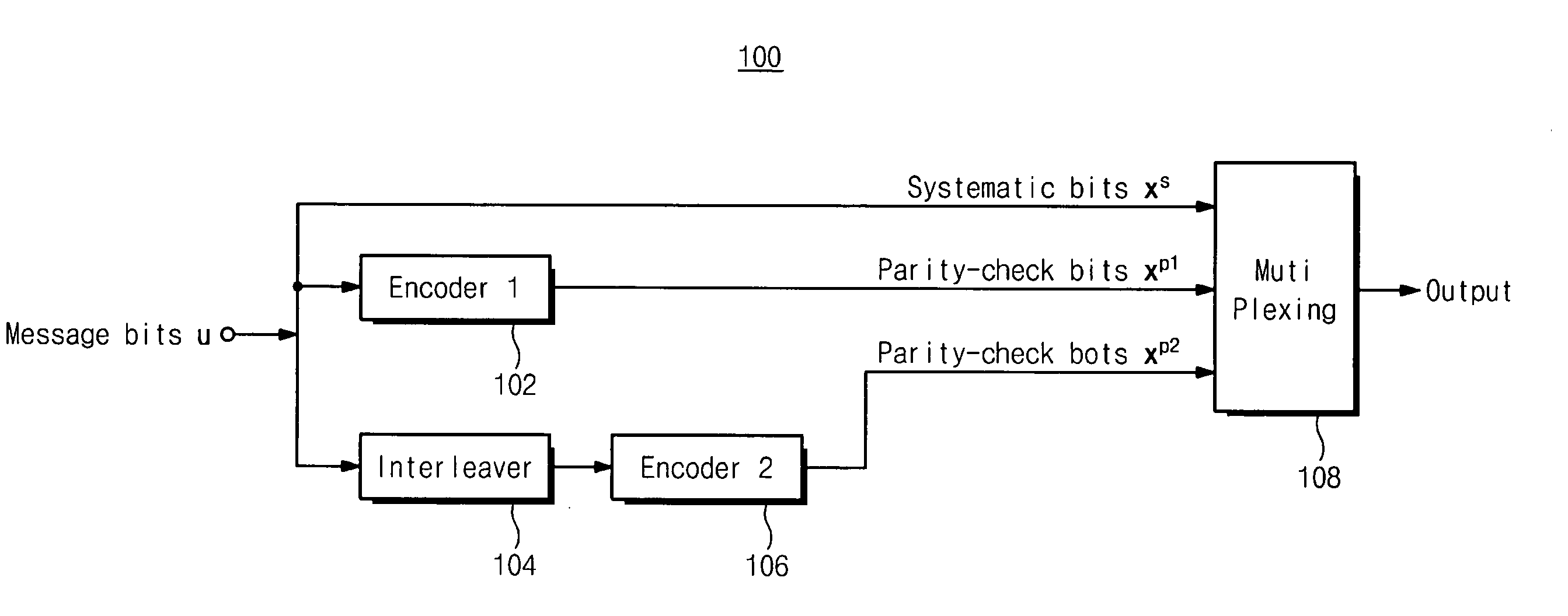
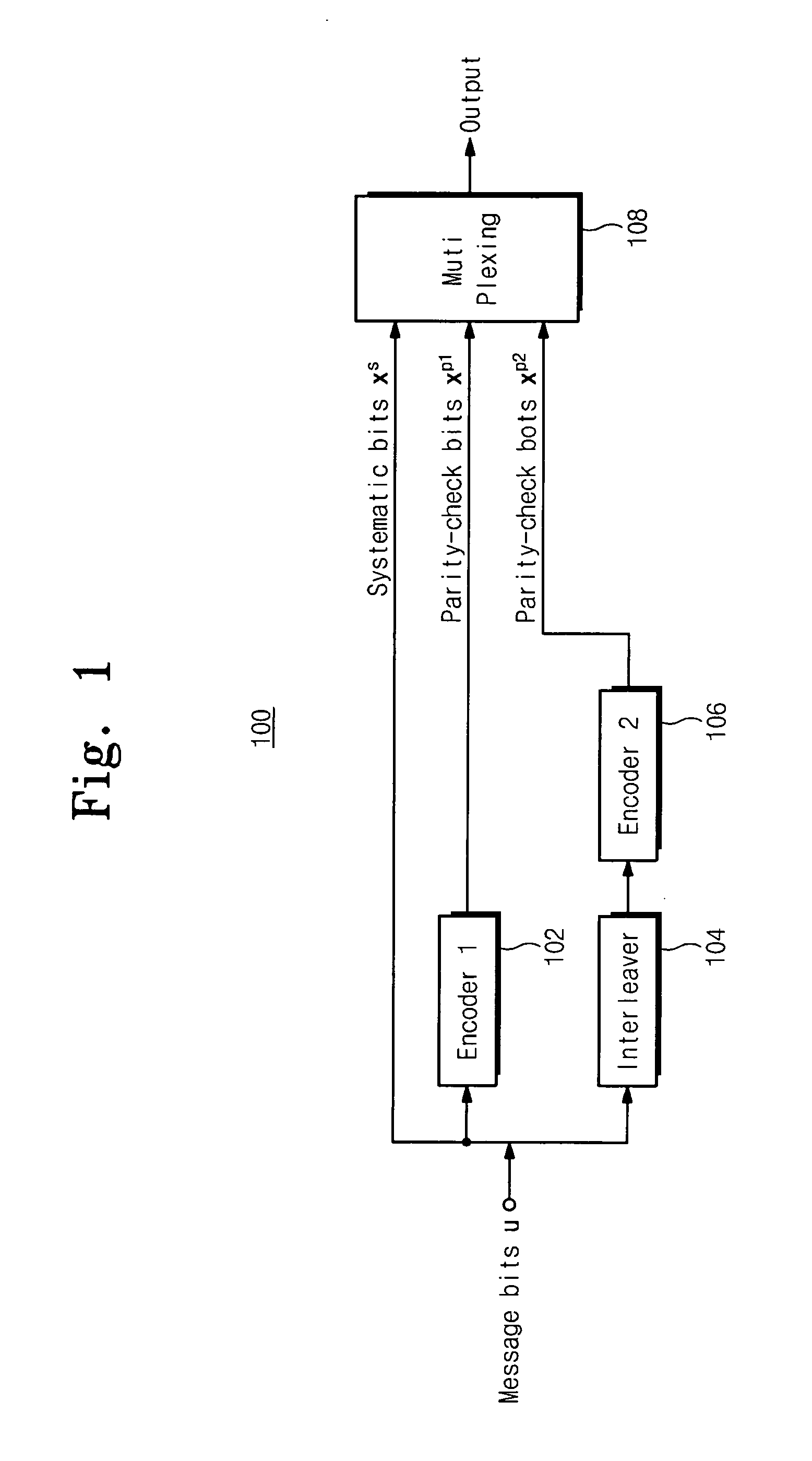
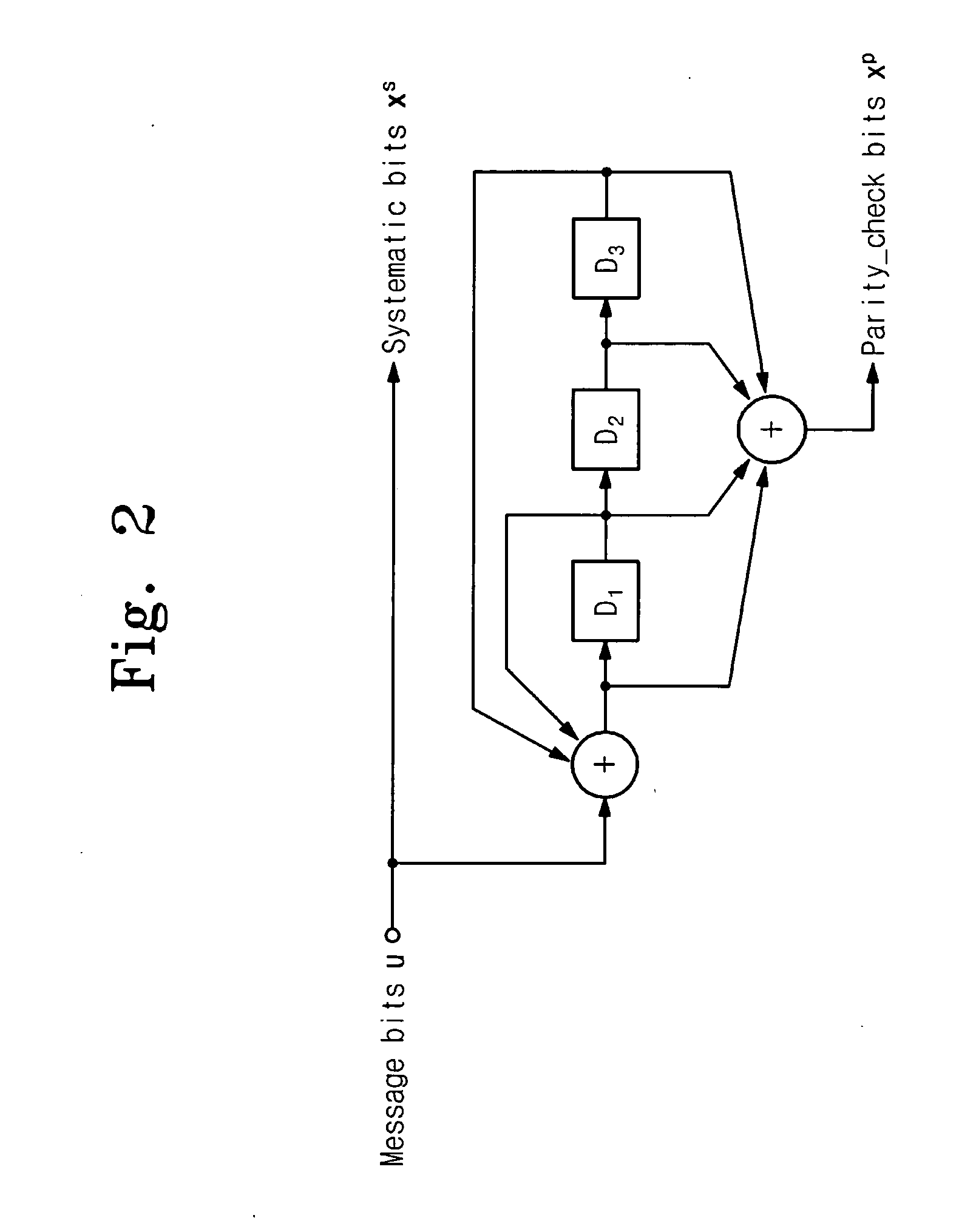
[0035]FIG. 1 illustrates a basic turbo-encoding system 100 and FIG. 2 illustrates a typical eight-state RSC encoder 102, 106 of FIG. 1.

[0036] The encoder of the turbo coding system consists of two constituent systematic encoders 102, 106 joined together by means of an interleaver 104. Input data str...


PUM


Abstract

A processor on which software interleaver is run is provided. The interleaver generation is split into two parts to reduce the overhead time of interleaver changing. First preprocessing prepares seed variables requiring a small memory. Second on-the-fly address generation generates interleaved address through simple adding and subtracting operations using the seed variables.

Description

TECHNICAL FIELD [0001] The present invention relates to a data processing system, and more particularly to a turbo decoder and a turbo interleaver. BACKGROUND OF THE INVENTION [0002] Data signals, in particular those transmitted over a typically hostile RF interface (communication channel), are susceptible to error (channel noise) caused by interface. Various methods of error correction coding have been developed in order to minimize the adverse effects that a hostile interface has on the integrity of communicated data. This is also referred to as lowering the Bit Error Rate (BER), which is generally defined as the ratio of incorrectly received information bits to the total number of received information bits. Error correction coding generally involves representing digital data in ways designed to be robust with respect to bit errors. Error correction coding enables a communication system to recover original data from a signal that has been corrupted. [0003] Error correction code in...

Claims


Application Information

Patent Timeline
IPC IPC(8): H03M13/00H03M13/37H03M13/27H03M13/29
CPCH03M13/276H03M13/2957H03M13/2771B60N3/023A62C3/07B60Y2200/143B60Y2200/31
Inventor SHIN, MYEONG-CHEOL
Owner SAMSUNG ELECTRONICS CO LTD
Learn More