Dental model tray used in forming dental model

a dental model and tray technology, applied in the field of dental models, can solve the problems of insufficient rigidity of individual dies, inability to use dies in forming precision prosthetics, and insufficient flexibility of polymeric pins, etc., and achieve the effect of convenient removal and replacement and exceptional accuracy

Inactive Publication Date: 2005-09-01
GARLAND JAMES K
View PDF3 Cites 1 Cited by
  • Summary
  • Abstract
  • Description
  • Claims
  • Application Information

AI Technical Summary

Benefits of technology

[0014] When casting material is poured around the projections, the heat produced by the setting of the casting material heats the polymeric material of the projections, and the projections expand. Then, as the set casting material cools, the projections shrink. However, when the particular structural characteristics of the present invention are maintained in the projections, it has been found that the expansion of the casting material during the setting and cooling can be used to offset the shrinkage of the polymeric material from which the projections are made. When the structural characteristics of the present invention are maintained, it has been found that the resulting dental model that is cast around the projections can be readily removed and replaced on the tray without sticking tightly to the projections. Further, it has also been quite unexpectedly found, that the cast dental model, and especially any dies that are cut from the model, will be held sufficiently on the tray by the projections to prevent the dental model and die or dies from falling from the tray as the tray is being used in forming the prosthetic device for one or more of the teeth of the dental model. The dies can be removed from the dental model and replaced, with the dies being relocated with exceptional accuracy relative to the remaining dental model.

Problems solved by technology

However, with pins made of polymeric material and having a similar size and shape as the metal pins of the trays of the prior art, the resulting pins made of polymeric material are too flexible and do not have sufficient rigidity.
A dental model can be cast on such pins, but when the dental model is cut into dies, and the dies are replaced on their mutually respective pins, the individual dies are not stable, i.e., the pins flex and allow the dies to move to and away from adjacent dies or adjacent portions of the model.
This is because the pins made of polymeric material are not sufficiently rigid, they flex and thus allow do not hold the dies firmly in their proper orientation.
When the pins are not sufficiently rigid to prevent the die from moving back and forth within that space formed by the saw cuts, then the die cannot be used in forming a precision prosthetic thereon, and the resulting dental model is not useful.

Method used


Image

  • Dental model tray used in forming dental model
  • Dental model tray used in forming dental model

Examples


Embodiment Construction

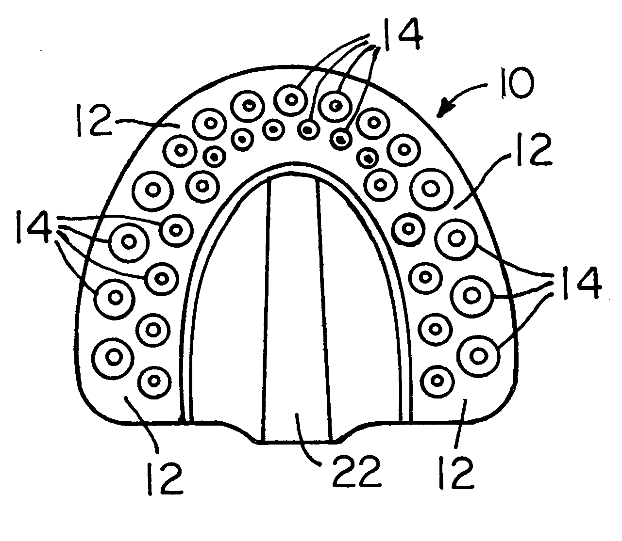
[0021] Referring now to FIGS. 1-3, a dental model tray 10 is shown. The tray 10 has a substantially planar base wall 12 upon which dental casting material (not shown in drawings) is poured informing a dental model. The base wall 12 if formed from a polymeric material and a plurality of spaced apart, elongate projections 14 are formed integrally with the base wall 12. The projections 14 extend upwardly from an upper face of the base wall 12 so that an elongate axis of each of the projections 14 is substantially perpendicular to the upper face of the base wall 12. The projections are advantageously molded integrally with the base wall 12 and are thus formed of the same polymeric material as the base wall 12.

[0022] The projections 14 are arranged in first and second rows that are substantially parallel with each other. The projections 14 in the first row are offset from corresponding projections 14 in the second row so that any two adjacent projections 14 in one row and an adjacent, c...


PUM


Abstract

Tray (10) for forming dental model comprises base wall (12) forming floor upon which dental casting material is poured. Spaced apart projections (14) extending upwardly from base wall (12). An upstanding axis of each projection (14) is substantially perpendicular to the upper face of the base wall (12). Projections (14) are arranged in two rows, with the projections (14) in one row being offset from corresponding projections (14) in the other row. Sidewalls of each projection (14) taper inwardly at an angle of between about 82 to 88 degrees with the upper face of the base wall (12). Each projection (14) has a thickness at its base of about 3 to 7 millimeters. The projections (14) are spaced from each other at their bases by a distance of from 0 to 5 millimeters.

Description

BACKGROUND OF THE INVENTION [0001] 1. Field of the Invention [0002] The present invention relates to trays used by laboratory technicians in making a dental model from casting material that is poured on the tray. [0003] 2. State of the Art [0004] Dental trays have been used in the prior art wherein casting material is poured on the tray and a dental model is then formed in the casting material. A system in the prior art utilized a plurality of metal pins that extended upwardly from the upper surface of the tray, with the casting material being poured over the pins. The resulting dental model could then be cut so as to isolate one or more dies corresponding to teeth upon which a crown or other prosthetic device was to be formed. The die or dies could then be placed back on the tray, and the correspondence of the pins extending from the tray into the die or dies would result in proper positioning of the die or dies relative to the dental model. [0005] A problem with the tray having me...

Claims


Application Information

Patent Timeline
Patent Type & Authority Applications(United States)
IPC IPC(8): A61C9/00
CPCA61C9/002
Inventor GARLAND, JAMES K.
Owner GARLAND JAMES K
Why Eureka
Try Eureka