Clock with an inserted base

a base and clock technology, applied in the field of clocks with bases, can solve the problems of increased manufacturing and shipping costs, unfavorable, and increased cost per unit of manufactur

Inactive Publication Date: 2005-08-18
DESIGN FACTORY
View PDF2 Cites 1 Cited by
  • Summary
  • Abstract
  • Description
  • Claims
  • Application Information

AI Technical Summary

Benefits of technology

[0012] These and other objects are attained by the present invention which is directed to a clock with an insertion base which is separately manufactured, e.g., molded, apart from the main body frame of the clock and then coupled to the clock in secure fashion. The insertion base can be provided with a visual illustration, e.g., by a purchaser such as a consumer, importer, wholesaler, and then coupled...

Problems solved by technology

This has undesirably increased cost per unit manufacture because of expenditures for providing printing blocks and the actual steps of printing upon the clock faces.
Additionally, the entire clock had to be assembled right at the clock factory, adding to increas...

Method used


Image

  • Clock with an inserted base
  • Clock with an inserted base
  • Clock with an inserted base

Examples


Embodiment Construction

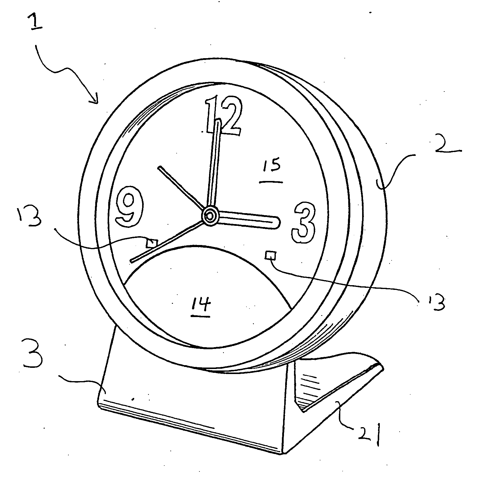
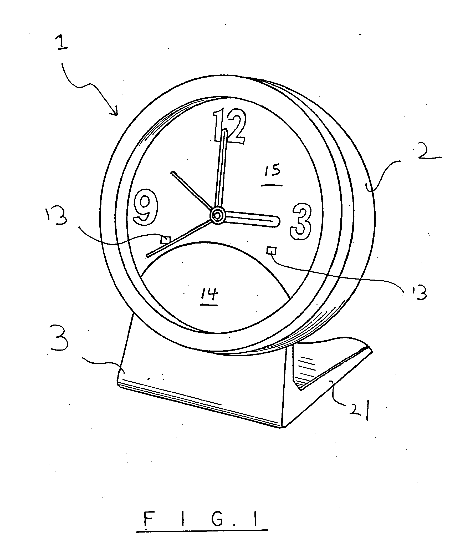
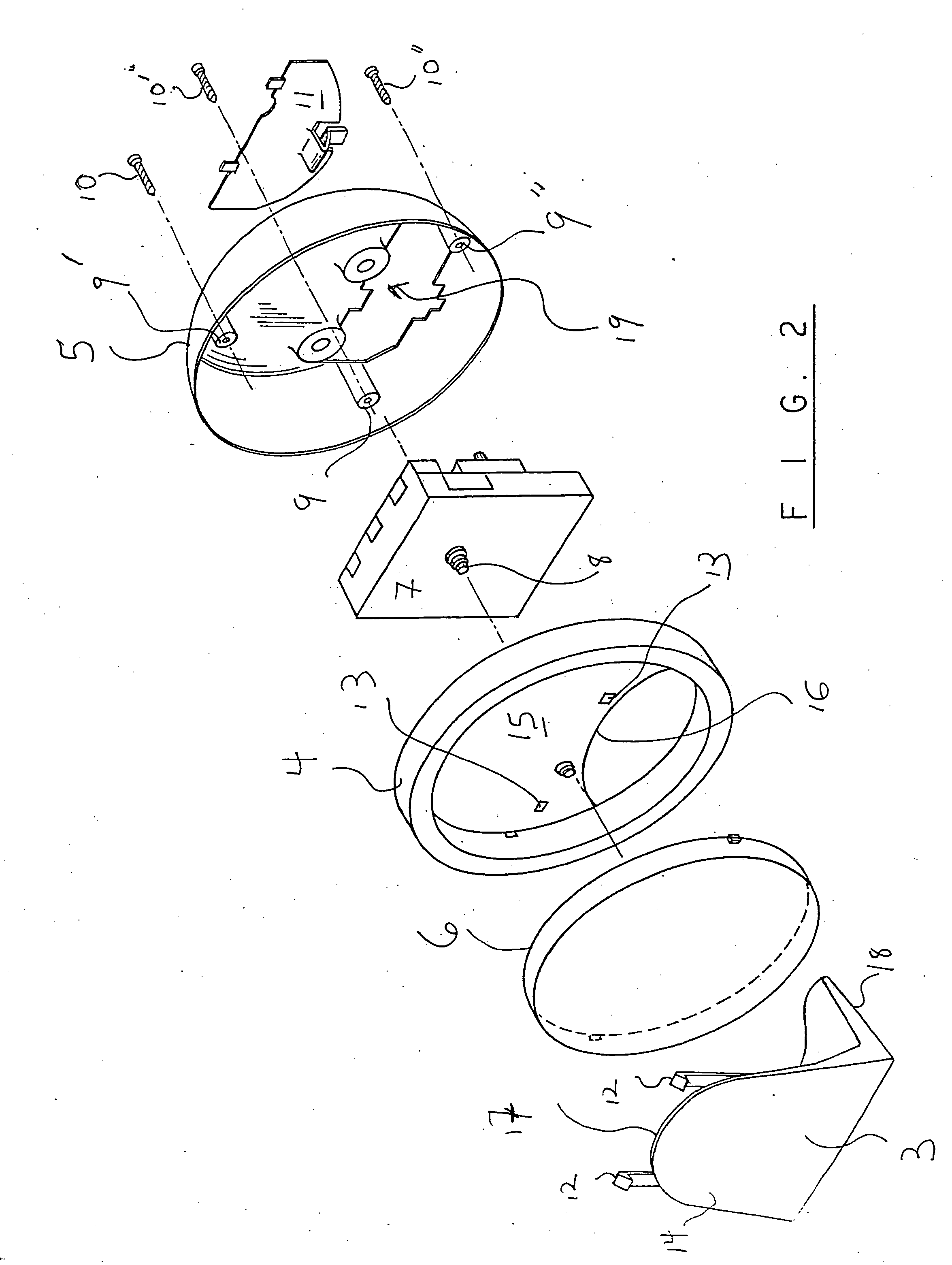
[0037] The clock 1 with an insertion base is shown in the perspective view of FIG. 1 as comprising a main body frame 2 and separate insertion base 3. As best seen in the exploded view of FIG. 2, the main frame body 2 comprises a front side or face 4 and a rear side or face 5 that are held together by screws 10, 10′, 10″ being threaded into respective raised bore holes 9, 9′, 9″. A clockwork mechanism 7, containing gears, is seated within and retained by main body members 4 and 5 of the main body frame 2 when coupled together, and comprises a spindle 8 rotatably extending therefrom and protruding through the hour plate or clock face 15 supported upon the front main frame member 4. The various pointers, e.g. hour, minute and second hands and an alarm-setting pointer, are rotatably positioned upon the spindle 8. Time and the alarm can be set by appropriately rotating spindles 23 and 24 protruding from the rear of the clockwork mechanism 7 and through the rear face 5 of the clock main f...


PUM


Abstract

A clock with an inserted base is provided to facilitate presenting various illustrations such as photographs, advertising copy, logos, etc., upon the surface of the clock face after purchase by a customer. The base is separately provided apart from the clock and then inserted into and coupled to the main clock frame which is then supported upon the base in upright position. In a preferred embodiment, the base is composed of a cover and insert rotatably coupled together so that the main clock frame is shielded by the cover in closed condition and supported upon the cover in open condition.

Description

CROSS REFERENCE TO RELATED APPLICATIONS [0001] The present application is a continuation-in-part of copending U.S. application Ser. No. 10 / 465,699 filed Jun. 19, 2003, the contents of which are incorporated by reference herein.BACKGROUND OF THE INVENTION [0002] The present invention is directed to a clock having a base which can be inserted into a main body frame of the clock after molding and be securely coupled thereto. [0003] Visual features such as logos or characters have been printed upon faces or hour plates of conventional clocks before assembly, at the clock factory itself. This has undesirably increased cost per unit manufacture because of expenditures for providing printing blocks and the actual steps of printing upon the clock faces. Costs especially increase when only a small shipment of specialty clocks with unique clock faces are ordered. Additionally, the entire clock had to be assembled right at the clock factory, adding to increase expense in manufacturing and ship...

Claims


Application Information

Patent Timeline
IPC IPC(8): G04B37/14
CPCG04B37/1473
Inventor YAMAZAKI, NOBUYUKIYAMASHITA, HISAE
Owner DESIGN FACTORY
Why Eureka
Try Eureka