
Imprinting apparatus with independently actuating separable modules

a technology of independent actuation and printing apparatus, applied in the direction of printing equipment, photomechanical equipment, instruments, etc., can solve the problems of increasing the number of defective products, defective products, and inability to use the conventional printing equipment using the first method

Active Publication Date: 2005-08-18
KOREA INST OF MASCH & MATERIALS
View PDF6 Cites 51 Cited by
  • Summary
  • Abstract
  • Description
  • Claims
  • Application Information

AI Technical Summary

Benefits of technology

The present invention provides an imprinting apparatus that can control the pattern of a material surface by using multiple imprinting modules that can be separated from each other. Each module has its own actuator that self-aligns with the surface of the material to compensate for any errors between the mold and the material. This ensures accurate patterning and reduces defective products.

Problems solved by technology

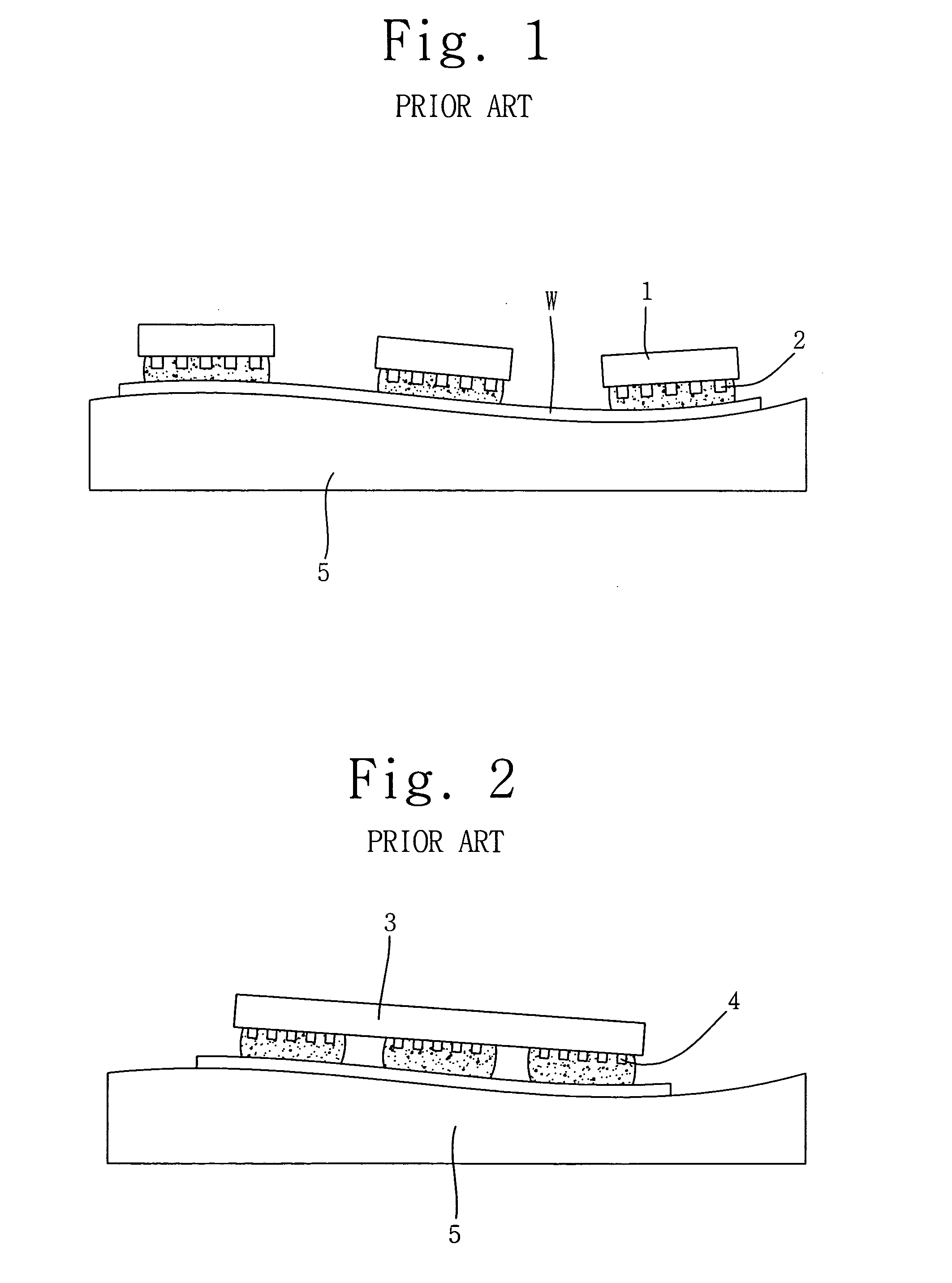
The technical problem addressed in this patent text is the limitations of conventional imprinting apparatuses in imprinting patterns on objective materials using either a single pattern or a single mold. These methods have limitations in terms of required imprinting time and accuracy, and cannot be used for different types of patterns. Additionally, the conventional methods may not evenly imprint the patterns on the objective material, resulting in defective products. The patent aims to provide a solution to these limitations and provide an improved method for imprinting patterns on objective materials.

Method used


Image

  • Imprinting apparatus with independently actuating separable modules
  • Imprinting apparatus with independently actuating separable modules
  • Imprinting apparatus with independently actuating separable modules

Examples


Embodiment Construction

[0032] Hereinafter, embodiments of the present invention will be described in detail with reference to the attached drawings.

[0033] Reference now should be made to the drawings, in which the same reference numerals are used throughout the different drawings to designate the same or similar components.

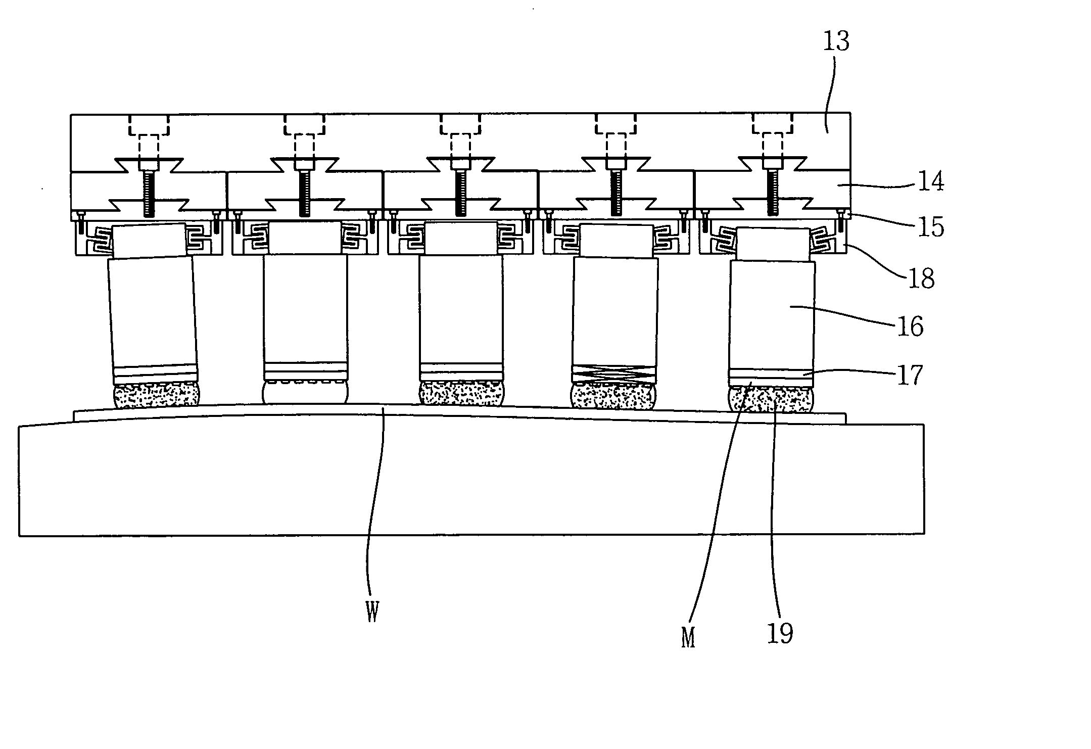
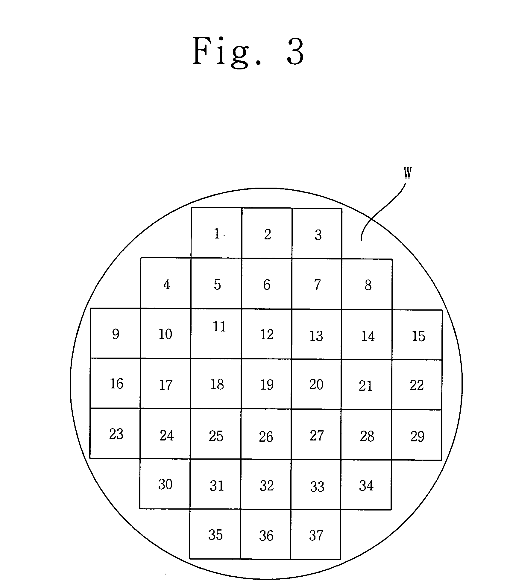
[0034] As shown in FIGS. 6 through 16, an imprinting apparatus 10 according to the present invention appropriately controls a range of imprinting patterns P on an objective material W while controlling the number of imprinting modules 12 each having the pattern P according to an area of the objective material W. Each of the plurality of imprinting modules 12 is provided to a plate unit 11 to be independently self-aligned in response to surface conditions of the objective material W by a controller (not shown). Thus, a relative pose error of each of the imprinting modules 12 with respect to the objective material W is compensated. Furthermore, a user controls a sequence along which the...


PUM

PropertyMeasurementUnit
Angleaaaaaaaaaa
Elasticityaaaaaaaaaa
Erroraaaaaaaaaa

Abstract

The present invention provides an imprinting apparatus, including a plate unit, and a plurality of imprinting modules provided on a lower surface of the plate unit. Each of the plurality of imprinting modules includes an actuator provided under the plate unit to be independently actuated by the controller, with a mold attached to a lower surface of the actuator and having a pattern on a lower surface thereof, so that the mold of the actuator is in surface contact with the upper surface of the objective material, a bonding unit to attach the mold to the lower surface of the actuator, and a compensator including an outer frame provided on the lower surface of the plate unit, and an inner frame placed in the outer frame so that the inner frame is self-aligned by the compliance of six degrees of freedom. The inner frame has on a lower end thereof the actuator, so that the actuator along with the inner frame executes a horizontal and vertical translational motion, a wobbling motion and a rotational motion in response to the conditions of the upper surface of the objective material when the pattern of the mold is imprinted on the upper surface of the objective material, thus compensating for a relative pose error of the mold with respect to the objective material.

Description


Claims


Application Information

Patent Timeline
Owner KOREA INST OF MASCH & MATERIALS
Learn More