
Bubble generating assembly

a technology of bubble generating assembly and assembly plate, which is applied in the field of bubble toys, can solve the problems of increasing the overall cost of the bubble generating assembly, unintended spillage, and increasing the likelihood of defects, and achieves the effect of forming a film

Inactive Publication Date: 2005-07-28
ARKO DEVMENT
View PDF11 Cites 0 Cited by
  • Summary
  • Abstract
  • Description
  • Claims
  • Application Information

AI Technical Summary

Benefits of technology

"The present invention provides an apparatus and method for effectively forming a film of bubble solution across a bubble ring while minimizing spillage. The apparatus has a simple construction and includes a bubble generating device, a trigger mechanism, a housing, a container, and a link assembly. The link assembly connects the trigger mechanism and the bubble generating device, allowing actuation of the trigger mechanism to cause the bubble generating device to move and create a film of bubble solution across the bubble generating device."

Problems solved by technology

Unfortunately, this continuous pouring and re-pouring of bubble solution from the bottle to the dish, and from the dish back to the bottle, often results in unintended spillage, which can be messy, dirty, and a waste of bubble solution.
Although such a design avoids some of the spillage problems described above, the construction of the bubble generating assembly in DeMars is quite complex, which increases the overall cost of the bubble generating assembly.
More importantly, the complex construction has many different moving and interengaging parts that increase the likelihood of defects.
Sadly, any defect with any part could mean that the entire assembly is not operational.
Depending on the size and quality of the motor, the single motor may not be able to simultaneously perform both tasks effectively, which may negatively affect the quality of the bubbles produced by the bubble generating assembly.

Method used


Image

  • Bubble generating assembly
  • Bubble generating assembly
  • Bubble generating assembly

Examples


Embodiment Construction

[0025] The following detailed description is of the best presently contemplated modes of carrying out the invention. This description is not to be taken in a limiting sense, but is made merely for the purpose of illustrating general principles of embodiments of the invention. The scope of the invention is best defined by the appended claims. In certain instances, detailed descriptions of well-known devices and mechanisms are omitted so as to not obscure the description of the present invention with unnecessary detail.

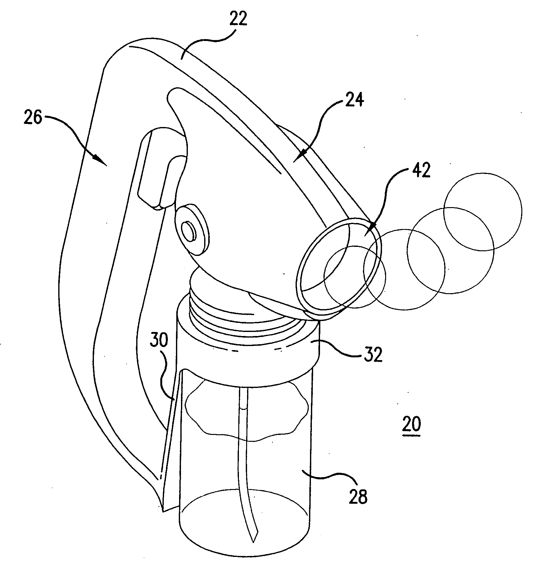
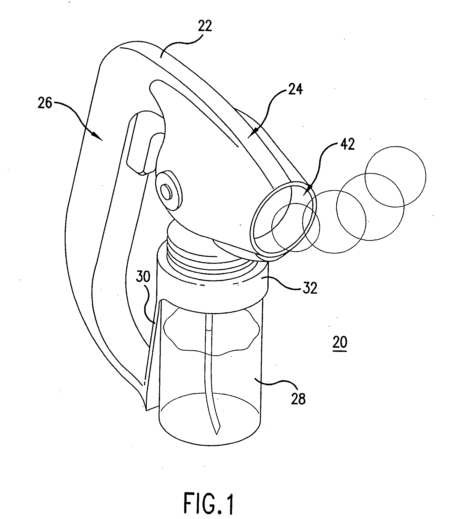
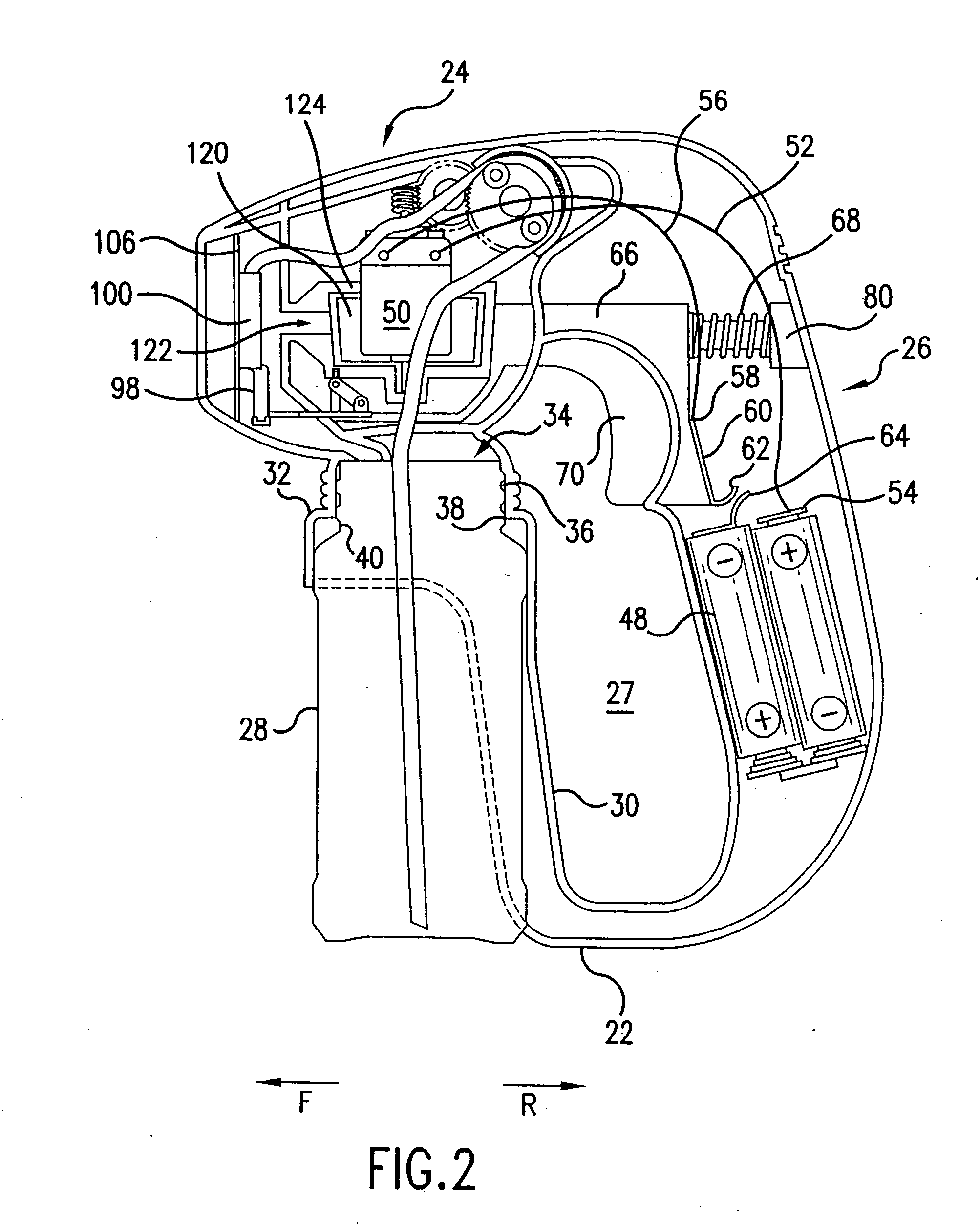
[0026]FIGS. 1-3 illustrate one embodiment of a bubble generating assembly 20 according to the present invention. The assembly 20 has a housing 22 that includes a handle section 26 and a barrel section 24. The housing 22 can be provided in the form of two symmetrical outer shells that are connected together by, for example, screws or welding or glue. These outer shells together define a hollow interior for housing the internal components of the assembly 20, as described...


PUM


Abstract

A bubble generating assembly has a housing, a container coupled to the housing and retaining bubble solution, a trigger mechanism, a bubble generating device, a tubing that couples the interior of the container with the bubble generating device, a stationary wiping bar that is fixed to the housing, and a link assembly housed inside the housing. The link assembly couples the trigger mechanism and the bubble generating device in a manner in which actuation of the trigger mechanism causes the bubble generating device to move past the wiping bar and to contact the wiping bar, so as to create a film of bubble solution across the bubble generating device.

Description

BACKGROUND OF THE INVENTION [0001] 1. Field of the Invention [0002] The present invention relates to bubble toys, and in particular, to a bubble generating assembly which automatically forms a bubble film over a bubble ring without the need to dip the bubble ring into a container or a dish of bubble solution. [0003] 2. Description of the Prior Art [0004] Bubble producing toys are very popular among children who enjoy producing bubbles of different shapes and sizes. Many bubble producing toys have previously been provided. Perhaps the simplest example has a stick with a circular opening or ring at one end, resembling a wand. A bubble solution film is produced when the ring is dipped into a dish that holds bubble solution or bubble producing fluid (such as soap) and then removed therefrom. Bubbles are then formed by blowing carefully against the film. Such a toy requires dipping every time a bubble is to created, and the bubble solution must accompany the wand from one location to ano...

Claims


Application Information

Patent Timeline
Patent Type & Authority Applications(United States)
IPC IPC(8): A63H33/28
CPCA63H33/28
Inventor THAI, DOUGLAS
Owner ARKO DEVMENT
Learn More